MCP Connector for AutoCAD Documentation
Complete guide to installing, configuring, and using MCP Connector for AutoCAD - 201 MCP tools, including the 43 free read-only tools, driven by Claude Desktop, ChatGPT Desktop, Cursor, or Claude Code.
Supported AutoCAD Versions
- AutoCAD 2022
- AutoCAD 2023
- AutoCAD 2024
- AutoCAD 2025
- AutoCAD 2026
- AutoCAD 2027
Full AutoCAD is required. AutoCAD LT is not supported. LT does not run add-ins, and the connector works as a plug-in inside AutoCAD. Windows 10 or 11, 64-bit.
AI Applications
- Claude Desktop
- ChatGPT Desktop
- Cursor
- Claude Code
- VS Code (GitHub Copilot agent mode)
- Visual Studio 2022 17.14+ / 2026 (GitHub Copilot)
- GitHub Copilot CLI
- Grok Build (xAI CLI)
Installation
Make sure all running instances of Autodesk AutoCAD are closed before starting the installation.
.exe file and follow the installation wizard, accepting the licence agreement and privacy policy. One install covers every supported AutoCAD release, so there is nothing to choose.MCPCONNECTOR_STATUS at the command line confirms it is running, and MCPCONNECTOR_START starts it if it is not.
Enabling MCP Connector for AutoCAD
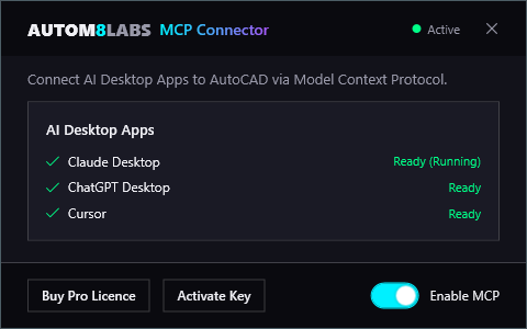
After installation, click the MCP Connector button in the Add-ins tab to open the connector dialog, then toggle Enable MCP to start the connection. No licence key is needed for the free tools - the key only unlocks the Pro set.
The dialog shows the status of detected AI applications:
- Ready (Running) - The AI application is configured to reach AutoCAD and is currently open
- Ready - Configured, but the application is not running right now
- Detected - The application is installed but not yet configured; toggle Enable MCP to configure it
- Not Detected - The AI application is not installed on this machine
The indicator at the top of the dialog reads Disabled, Waiting, or Active. Toggling Enable MCP off again removes the connector from every detected client's configuration.
Configuration
MCP Connector for AutoCAD includes one-click auto-configuration for supported AI applications. Toggling Enable MCP in the connector dialog writes the configuration for every detected application at once. The installer also registers the server on install, so in most cases there is nothing to do by hand.
Claude Desktop
The config file is located at:
%APPDATA%\Claude\claude_desktop_config.json
The Microsoft Store build never reads %APPDATA%\Claude - Windows redirects that folder into a sandboxed package location. MCP Connector for AutoCAD detects the Store package and writes to both paths, so the Store build is configured automatically. The redirected file lives here:
%LOCALAPPDATA%\Packages\Claude_<hash>\LocalCache\Roaming\Claude\claude_desktop_config.json
If tools still do not appear, fully quit Claude from the system tray (closing the window is not enough) and reopen it.
ChatGPT Desktop
ChatGPT appears in the dialog when it is installed on your machine. The config file is located at:
%USERPROFILE%\.codex\config.toml
This file is shared with the Codex CLI, so configuring ChatGPT Desktop makes the AutoCAD tools available in Codex CLI as well. After configuring, fully quit ChatGPT and reopen it. With AutoCAD open and a drawing loaded, a quick test is to ask ChatGPT to "ping AutoCAD".
Use Work, not Chat. ChatGPT Desktop loads MCP servers from this config file in its Work area only - regular Chat conversations cannot see the AutoCAD tools. If ChatGPT replies that the AutoCAD MCP is not connected, check you are in Work first, then start a fresh conversation - the MCP connection is per-conversation and drops after sitting idle.
Cursor
The config file is located at:
%USERPROFILE%\.cursor\mcp.json
GitHub Copilot
GitHub Copilot appears in the dialog when VS Code, Visual Studio, or the Copilot CLI is installed on your machine. The config files are located at:
%APPDATA%\Code\User\mcp.json
%USERPROFILE%\.mcp.json
%USERPROFILE%\.copilot\mcp-config.json
Grok Build
Toggle Enable MCP and the connector writes its entry into xAI's Grok Build CLI configuration automatically. The config file is located at:
%USERPROFILE%\.grok\config.toml
Grok Build also reads Claude Code's and Cursor's MCP config, so if you have already configured either of those the connector shows up in Grok Build with no extra step.
Claude Code & other MCP clients
MCP Connector for AutoCAD exposes a standard MCP stdio server, so it also works with Claude Code, VS Code, and any other MCP-compatible client. The server is a single executable installed with the plug-in bundle:
C:\Program Files\Autodesk\ApplicationPlugins\AUTOM8LABS.MCPConnectorAutoCAD.bundle\Contents\Bridge\MCPConnectorAutoCAD.Bridge.exe
Register it in Claude Code from a terminal:
claude mcp add AUTOM8LABS_AutoCAD -- "C:\Program Files\Autodesk\ApplicationPlugins\AUTOM8LABS.MCPConnectorAutoCAD.bundle\Contents\Bridge\MCPConnectorAutoCAD.Bridge.exe"
Manual configuration (any MCP client)
Add this to your client's MCP server configuration:
{
  "mcpServers": {
    "AUTOM8LABS_AutoCAD": {
      "command": "C:\\Program Files\\Autodesk\\ApplicationPlugins\\AUTOM8LABS.MCPConnectorAutoCAD.bundle\\Contents\\Bridge\\MCPConnectorAutoCAD.Bridge.exe"
    }
  }
}
VS Code
VS Code uses a slightly different shape. Add the server to your MCP configuration (for example .vscode/mcp.json in a workspace):
{
  "servers": {
    "AUTOM8LABS_AutoCAD": {
      "type": "stdio",
      "command": "C:\\Program Files\\Autodesk\\ApplicationPlugins\\AUTOM8LABS.MCPConnectorAutoCAD.bundle\\Contents\\Bridge\\MCPConnectorAutoCAD.Bridge.exe"
    }
  }
}After changing MCP configuration, restart the AI client completely for the changes to take effect.
Optional: raw command execution
Two tools can drive AutoCAD directly: execute_command runs a raw AutoCAD command string as if
typed at the command line, and execute_lisp evaluates an AutoLISP expression. Because they
can drive anything, both are disabled by
default: they are neither listed nor callable until you opt in on that machine by
setting MCP_CONNECTOR_ENABLE_COMMAND_EXEC=1 in the MCP client configuration.
Even when enabled, code-loading and shell verbs (NETLOAD, APPLOAD, SCRIPT, SHELL, AutoLISP
load) are blocked. Both tools are Pro, so a licence is needed as well as the opt-in.
After saving the configuration, fully quit and reopen your AI client - quit it from the system tray rather than just closing the window, or it keeps the old environment and the two tools still will not appear. To turn them off again, remove the setting and restart the client the same way.
{
  "mcpServers": {
    "AUTOM8LABS_AutoCAD": {
      "command": "C:\\Program Files\\Autodesk\\ApplicationPlugins\\AUTOM8LABS.MCPConnectorAutoCAD.bundle\\Contents\\Bridge\\MCPConnectorAutoCAD.Bridge.exe",
      "env": {
        "MCP_CONNECTOR_ENABLE_COMMAND_EXEC": "1"
      }
    }
  }
}
Optional: read-only session
A read-only session withholds every tool that can change a drawing, leaving the free read-only set: query, inspect, measure and navigate. A withheld tool is not listed to the AI client at all, and is refused by name if it is called anyway, so the AI cannot reach a write.
It is worth using whenever the drawings belong to a client rather than to you. DWG is usually the format that arrives from someone else. An in-session change can still be undone in AutoCAD, but the folder tools save each drawing as they go, so those edits are on disk already - and an unwanted change does not always announce itself on screen.
Turn it on with the Read-Only Session checkbox in the connection
dialog, or by running MCPCONNECTOR_READONLY at the AutoCAD command line.
Either way, reconnect your AI client afterwards so it refreshes its
tool list.
Locking it on for a team. An administrator can enforce read-only across a machine, so it applies to every user and cannot be switched off locally. That is a deployment setting rather than something to set up per seat - get in touch and we will send you the policy and how to apply it.
Claude Desktop Settings
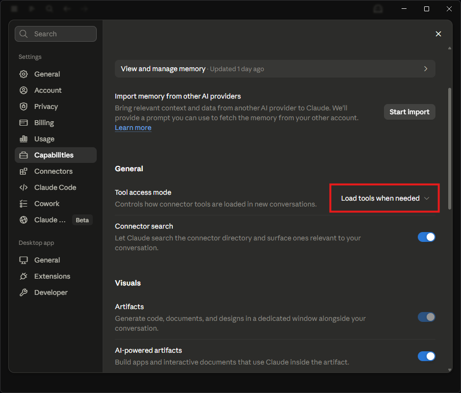
MCP Connector for AutoCAD exposes 201 tools, plus two optional command-execution tools that stay disabled until you opt in. In Claude Desktop, enable Load tools when needed so tools are loaded on demand rather than all at once.
Use Chat, not Cowork
Claude Desktop has a mode selector at the bottom of the message box: Chat and Cowork. MCP connectors run in Chat conversations. In Cowork, your AutoCAD requests will not reach the connector and Claude behaves as if AutoCAD is not connected - even though the connector is configured correctly. Before you start, check the selector is set to Chat.
Note this is the opposite way round to ChatGPT Desktop, where the AutoCAD tools are available in Work rather than regular Chat.

Local AI Setup
Connect a local AI model to AutoCAD through an MCP-compatible app. These steps are for Windows, on the same computer as AutoCAD.
1. Prepare AutoCAD
- Install MCP Connector for AutoCAD and open a sample drawing.
- On the Add-ins tab, click MCP Connector and turn on Enable MCP. Keep AutoCAD open.
- In your AI app, download or select a local model that supports tool calling.
2. Configure your app
Use this entry for AutoCAD 2022 to 2027.
{
  "mcpServers": {
    "AUTOM8LABS_AutoCAD": {
      "command": "C:\\Program Files\\Autodesk\\ApplicationPlugins\\AUTOM8LABS.MCPConnectorAutoCAD.bundle\\Contents\\Bridge\\MCPConnectorAutoCAD.Bridge.exe"
    }
  }
}
For separate fields, use AUTOM8LABS_AutoCAD as the name, stdio as the transport, and the command path with single backslashes and no quotes. Leave Arguments blank for this example.
Edit an existing connector entry rather than adding a duplicate. Keep its arguments, environment and tool settings. In an existing JSON file, add only AUTOM8LABS_AutoCAD inside mcpServers, preserving other entries.
Choose your app below. Connection tested means registration, tool discovery and reconnection were checked using the Revit connector. These AutoCAD steps use the same app settings; they have not been tested end to end with every app and model.
- Open Settings > Agent Skills once to create the configuration file.
- Click the app version number > Open storage. Open
plugins/anythingllm_mcp_servers.jsonand add the entry. - Return to Agent Skills and click Refresh. Check the connector is running.
- Start your test prompt with
@agent.
- Open MCP connections and look for
AUTOM8LABS_AutoCAD, including paused entries. - Use that connection if present. Otherwise, add one using the name and command above.
- Enable the connection and choose your local model.
- Open Settings > MCP > MCP Servers > Add > Import from JSON.
- Paste the JSON, enable the server and check its tools appear.
- Open Work > your Agent's menu > Edit > MCP and enable the connector for that Agent.
- Select your local model and start a conversation with that Agent.
- Open Settings > MCP Servers > Add MCP Server.
- Select STDIO and enter the name and command above.
- Save, then enable the server. A green indicator confirms it is active.
- In the right sidebar, open Program > Install > Edit mcp.json.
- Add the connector inside
mcpServersand save. - Check the connector is available and enabled for your chat.
- Sign in to your local installation. Open MCP settings > Import JSON.
- Paste the JSON. The import applies immediately.
- Enable the connector and MCP tool use for your chat.
These steps apply to 2026.9.11. Other versions may differ. See Unsloth's current guide.
3. Test the connection
With your sample drawing open, ask:
Use the AutoCAD connector to tell me the active drawing name and AutoCAD version. Do not change anything.
In AnythingLLM, prefix this with @agent. Confirm a connector tool runs and the answer matches your open drawing.
Tool loading and model limits
If available, enable tool selection or on-demand loading and start with a few read-only tools. Large tool lists can exceed a local model's context. A larger context setting alone does not guarantee reliable tool use.
Operator Skill
MCP Connector for AutoCAD ships with a free operator skill - a plain text playbook Claude reads before touching your drawing. It teaches Claude to use the connector efficiently: read in bulk instead of one entity at a time, verify answers with counts, batch edits in one call, and say so instead of guessing when something cannot be done. The result is fewer calls, fewer dead chats, and far less of your usage allowance burned on a single question.
Install in Claude Desktop:
- Download the skill: autocad-connector.zip
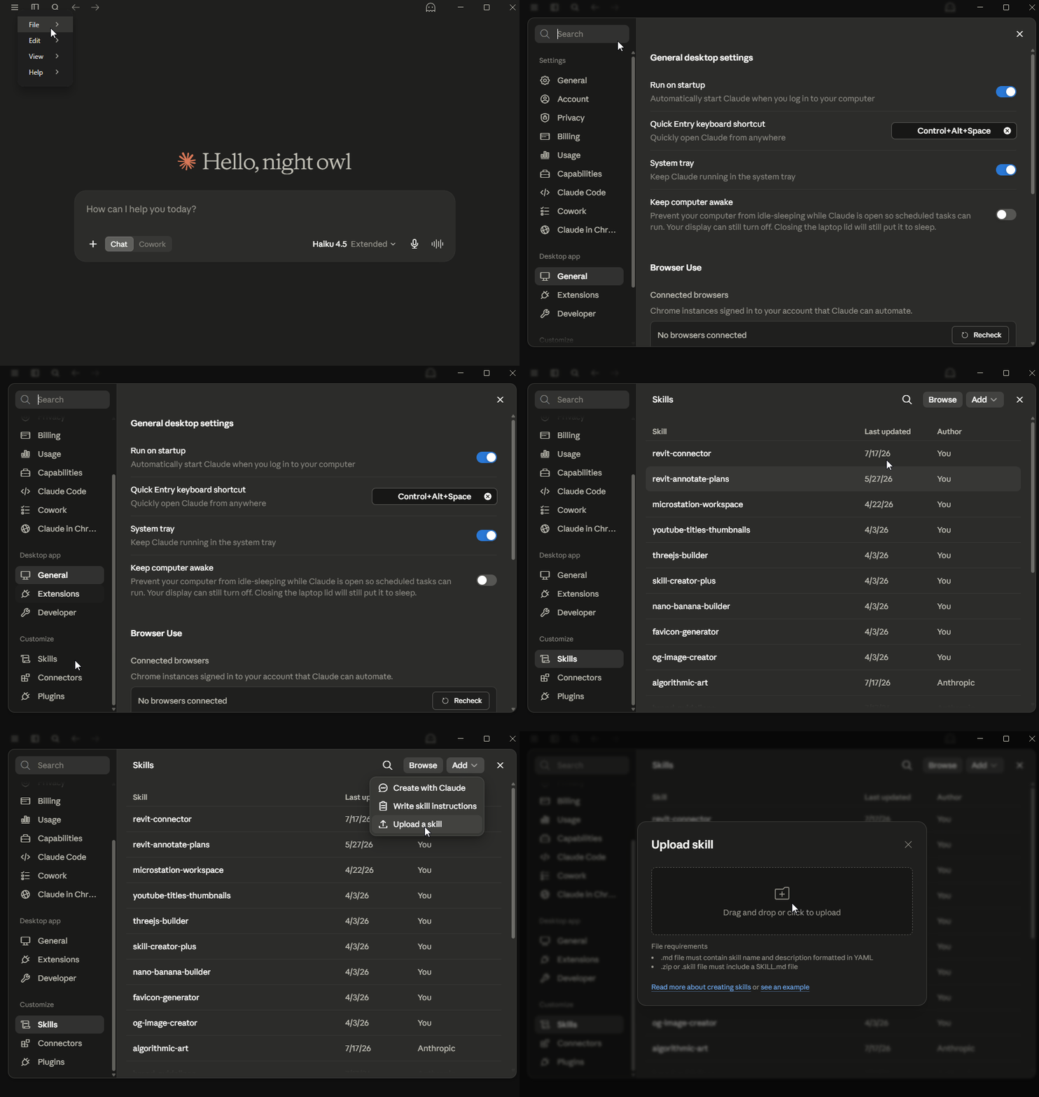
- In Claude Desktop, go to Settings > Skills > Add > Upload a skill and select the zip.
- That is it - Claude picks the skill up automatically in new chats. If you ever find it has not, mention it in your prompt, for example "Follow the autocad-connector skill".
Using Claude Code or Cursor instead? Install steps for both are in the mcp-connector-skills repository, which also hosts free skills for the rest of the MCP Connector family.
Quickstart
MCPCONNECTOR_STATUS confirms it is running.ping tool. You should get back "Connected to AutoCAD."Power BI Dashboard
A free browser dashboard and Power BI report for tool-use records. MCP Connector Pro is required to record audit logs.
Tool Use Audit dashboard
Review AI-assisted work in AutoCAD using a browser dashboard or Power BI.
Requires: MCP Connector for AutoCAD Pro 2.2.0+ and administrator rights to enable logging.
Download: Tool Use Audit v1.0.0 (.zip)
1. Enable logging
Logging is off by default. On each computer, open Registry Editor as administrator. Create this key if needed, then set its values:
HKEY_LOCAL_MACHINE\SOFTWARE\AUTOM8LABS\MCPConnectorAutoCAD
| Value name | Type and setting |
|---|---|
AuditLog | DWORD (32-bit): 1 |
AuditLogFolder | String (REG_SZ): your log folder, e.g. C:\AuditLogs |
Create the log folder and give AutoCAD users write access. For multiple computers, use a network share. Restart AutoCAD.
2. Open a dashboard
Extract the ZIP to C:\AuditDashboard or another short path. Keep its files and folders together.
- Open
audit-dashboard.htmlin Chrome or Edge. - Select Open audit folder, choose your
AuditLogFolderand allow read access.
The dashboard reads files locally and refreshes automatically.
- Open
AUTOM8LABS Connector Audit.pbipin Power BI Desktop for Windows (September 2026 or later). - Under Transform data > Edit parameters, set AuditLogFolder to your log folder.
- Select OK > Apply changes > Refresh.
Select Refresh whenever you want the latest records.
3. Check logging works
Ask your AI assistant to run get_drawing_info in your open AutoCAD drawing. Wait around 30 seconds, then check for the call. Select Refresh in Power BI.
Time, user, computer, host and release, drawing, AI app, tool, read/write type and outcome, plus the first 300 characters of its arguments. Chat messages, full tool results and bridge-only connection calls are excluded.
Write means the tool can change a drawing; it does not prove a change occurred. Optional: set AuditReason (DWORD) to 1 in the same registry key, then restart AutoCAD, to request a short explanation from the AI.
CSV files are saved under %LOCALAPPDATA%\AUTOM8LABS\MCPConnectorAutoCAD\Audit, then copied into month folders under AuditLogFolder every 30 seconds and when AutoCAD closes. Failed copies retry automatically for files updated within the last seven days.
Local copies are kept for 90 days. Files in your chosen folder are not automatically deleted. See the included README for more detail.
Want your company branding? Contact us.
Tool Reference
MCP Connector for AutoCAD adds its full tool set, grouped by category below, including a read-only free tier that works without a licence. Every tool name shown is the exact identifier exposed to your AI client. The Edition column shows whether a tool is available in the free edition or needs a Pro licence. A tool marked Opt-in does not register at all until you enable it - see raw command execution. Under each description is an example prompt showing how to ask for it in natural language - click any prompt to copy it, paste it into your AI client, and adjust the names and numbers to suit your drawing.
3D Solids
| Tool | Example prompt | Edition |
|---|---|---|
| Keep the common volume of two solids | ||
boolean_intersect | Keep only the volume where those two solids overlap | Pro |
| Subtract one solid from another | ||
boolean_subtract | Subtract the door opening solid from the wall solid | Pro |
| Unite two 3D solids into one | ||
boolean_union | Union the two selected solids into one | Pro |
| Create a solid box from a corner point and dimensions | ||
create_3d_box | Create a solid box at 0,0,0 measuring 6000 by 4000 by 3000 | Pro |
| Create a solid cone from base centre, base radius, and height | ||
create_3d_cone | Create a cone at 0,0 with a 750 base radius and 2000 height | Pro |
| Create a solid cylinder from centre point, radius, and height | ||
create_3d_cylinder | Create a 300 radius column 3600 tall at 2000,2000 | Pro |
| Create a solid sphere from centre point and radius | ||
create_3d_sphere | Create a 500 radius sphere at 1000,1000,2000 | Pro |
| Create a solid torus from centre, major radius, and minor radius | ||
create_3d_torus | Create a torus at 0,0,1000 with a 1500 major radius and a 100 tube radius | Pro |
| Create a solid wedge from a corner point and dimensions | ||
create_3d_wedge | Create a wedge at 0,0,0 measuring 2000 by 1000 by 800 | Pro |
| Extrude a closed 2D profile into a solid along a direction or path | ||
create_extrusion | Extrude the selected closed polyline up 3000 to make a wall solid | Pro |
| Create a cross-section region where a plane intersects a solid | ||
section_solid | Cut a horizontal section region through the solid at 1200 above its base | Pro |
| Slice a solid with a plane, optionally keeping both halves | ||
slice_solid | Slice the solid vertically at X=3000 and keep both halves | Pro |
Annotation
| Tool | Example prompt | Edition |
|---|---|---|
| Create an aligned dimension measuring true distance at any angle | ||
create_dimension_aligned | Add an aligned dimension along the sloping wall between those two ends | Pro |
| Create an angular dimension between two lines or from three points | ||
create_dimension_angular | Dimension the angle between the two selected lines | Pro |
| Create a horizontal or vertical dimension between two points, or a whole chain along a wall with the overall in one call | ||
create_dimension_linear | Dimension horizontally between 0,0 and 6000,0 with the dimension line at 0,-800 | Pro |
| Create a radius or diameter dimension on a circle or arc | ||
create_dimension_radius | Add a radius dimension to the selected arc | Pro |
| Create a multileader with an arrow and text annotation | ||
create_leader | Add a leader pointing at 3200,1800 with the text 150mm blockwork | Pro |
| Draw a revision cloud around a rectangle, a polygon, or an existing closed entity | ||
create_revcloud | Cloud the area around the revised bathroom layout | Pro |
| Create a table in a table style with rows, columns and cell data, per-table text heights and margins, and a read-back of the laid-out format | ||
create_table | Create a 6 row by 4 column door schedule at 12000,0 with the headers Mark, Width, Height, Type | Pro |
| Create a wipeout mask so annotation stays legible over hatching | ||
create_wipeout | Put a wipeout behind that note so it reads over the hatch | Pro |
| List the annotation scales defined in the drawing and which one is current | ||
list_annotation_scales | What annotation scales does this drawing have? | Free |
| Measure the width and height text takes up in its style, for text in the drawing or a line not yet placed | ||
measure_text | How wide would GROUND FLOOR PLAN be at 5 mm high in the Standard style? | Free |
| Make text, dimensions and multileaders annotative and give them the scale representations they appear at | ||
set_annotative | Make the room notes annotative at 1:50 and 1:100 | Pro |
| Change what a text or MText object is justified about, leaving it where it is | ||
set_text_justification | Make the selected room labels middle-centre justified without moving them | Pro |
Blocks
| Tool | Example prompt | Edition |
|---|---|---|
| Count insertions of a block, optionally grouped by layer | ||
count_block_references | How many door blocks are in this drawing, grouped by layer? | Free |
| Create a new block definition from existing entities | ||
create_block_definition | Turn the selected entities into a block called DETAIL-01 with its base point at 0,0 | Pro |
| Delete a block definition that nothing uses. One that is still in use is refused, with where it is used | ||
delete_block_definition | Delete the unused block definition OLD-TITLE | Pro |
| Read attribute definitions and values from a block reference | ||
get_block_attributes | Read the attributes off the selected title block | Free |
| Read what a block definition contains: its entities, extents, units and where it is used | ||
get_block_definition | What is inside the block DOOR-900, and where is it used? | Free |
| Read a dynamic block's visibility states, flips, lookups and sizes, with the values each allows | ||
get_dynamic_block_properties | What sizes and swing options does that door block offer? | Free |
| Import block definitions from another DWG, with the unit scale handled, and place them in the same call | ||
import_blocks | Bring the door and window blocks in from the office library DWG and place a 900 door at 4500,2000 | Pro |
| Insert a block reference with scale, rotation, and attribute values | ||
insert_block | Insert the DOOR-900 block at 4500,2000 rotated 90 degrees | Pro |
| List block definitions with entity counts, attributes, and xref status | ||
list_blocks | List every block in this drawing with how many entities it has and whether it carries attributes | Free |
| Rename a block definition, with every reference following it | ||
rename_block | Rename the block DOOR-01 to DOOR-EXTERNAL | Pro |
| Swap block references from one definition to another, keeping position, rotation and attributes | ||
replace_block | Replace every WINDOW-OLD block with WINDOW-2G and keep the attributes | Pro |
| Set an attribute value on a block reference by tag name | ||
set_block_attribute | Set the DRAWN_BY attribute on the selected title block to JG | Pro |
| Set a dynamic block's visibility state, size, flip or lookup value | ||
set_dynamic_block_properties | Change that door to 900 wide with the swing flipped | Pro |
Connectivity
| Tool | Example prompt | Edition |
|---|---|---|
| After a call whose result could not be confirmed, record that the affected drawing has been checked so that work can carry on. The call is never repeated automatically. | ||
acknowledge_bridge_recovery | I have checked the drawing and the last change did go in - acknowledge it and carry on | Free |
| Read whether a call is waiting to be checked because its result could not be confirmed, and what to inspect first. It changes nothing. | ||
get_bridge_recovery | Did that last call finish? What should I check before carrying on? | Free |
| Report on the current session: the connector version and edition, the AutoCAD release, the active drawing, how many tools the session offers, whether it is read-only, and the administrator policy in force | ||
get_session_info | Which connector version and edition is this, and is the session read-only? | Free |
| Check that the AI client can reach a running AutoCAD session | ||
ping | Ping AutoCAD and tell me if you are connected | Free |
Drawing and Document
| Tool | Example prompt | Edition |
|---|---|---|
| Make another open drawing the active one, confirmed once AutoCAD has switched | ||
activate_drawing | Switch to Site-Plan.dwg, which is already open | Pro |
| Audit the drawing database and optionally fix errors | ||
audit_drawing | Audit this drawing and fix any database errors you find | Pro |
| Close an open drawing, saving it first or discarding its changes when you say so | ||
close_drawing | Save and close Detail-03.dwg | Pro |
| Copy entities and paste them at their original coordinates, within or between drawings | ||
copy_to_original_coordinates | Copy the selected setting-out lines into Site-Plan.dwg at their original coordinates | Pro |
| Mark a point to roll back to, optionally saving a copy of the drawing first | ||
create_checkpoint | Set a checkpoint and save a backup copy before you start the layer clean-up | Pro |
| Detect likely drawing units by inspecting extents, entity sizes, and system variables | ||
detect_units | This survey DWG has no units set - work out what the units really are from the extents and entity sizes | Free |
| Read drawing information: file path, units, extents, layer and entity counts Extents come from the current model-space entities, including unsaved creations, with measured and excluded counts. | ||
get_drawing_info | What are the units, extents, and layer and entity counts for this drawing? | Free |
| Read the value of an AutoCAD system variable | ||
get_system_variable | What is DIMSCALE set to in this drawing? | Free |
| List every drawing open in this AutoCAD session: its path, which one is active, unsaved changes and read-only state | ||
list_open_drawings | Which drawings do I have open, and which have unsaved changes? | Free |
| Create a new blank drawing, optionally from a template | ||
new_drawing | Start a new drawing from our A1 template at C:\Standards\A1-Sheet.dwt | Pro |
| Open a DWG, DXF or DWT file, or switch to it if already open | ||
open_drawing | Open C:\Project\DWG\Site-Plan.dwg | Pro |
| Purge unused named objects to reduce file size | ||
purge_drawing | Purge every unused block, layer, and style from this drawing | Pro |
| Redo changes that were just undone (call it straight after undo) | ||
redo | Actually that was right, redo it | Pro |
| Revert every change made since the last checkpoint, in one step | ||
rollback_checkpoint | That has gone wrong, roll everything back to the checkpoint | Pro |
| Save the drawing, optionally to a new DWG or DXF path | ||
save_drawing | Save this drawing as a 2018 format DWG to C:\Project\Issue\Plan-A.dwg | Pro |
| Set an AutoCAD system variable to a new value | ||
set_system_variable | Set LTSCALE to 0.5 and turn FILEDIA back on | Pro |
| Set linear and angular units, insertion scale, and display precision | ||
set_units | Set this drawing to millimetres with 2 decimal places and degrees for angles | Pro |
| Undo the last changes, one tool call per step | ||
undo | Undo the last three things you did | Pro |
| Write selected entities to a new DWG file, keeping their coordinates | ||
write_block | Write everything on the survey layers to C:\Project\Xref\Survey-Extract.dwg, keeping the coordinates | Pro |
Entities and Selection
| Tool | Example prompt | Edition |
|---|---|---|
| Delete a named selection set; the entities themselves are untouched | ||
delete_selection_set | Delete the saved selection set called Fire strategy | Pro |
| List entities, filtered by type, layer, or bounding box, with pagination | ||
get_entities | List every polyline on the layer A-WALL with its layer and geometry | Free |
| Read full details of a specific entity by its handle | ||
get_entity_by_handle | Give me the full details of entity 2A7F | Free |
| Count entities, optionally broken down by type or layer | ||
get_entity_count | How many entities are in this drawing, broken down by layer? | Free |
| Read the full property set of one or more entities | ||
get_entity_properties | Read the full properties of the selected entities including linetype and lineweight | Free |
| Read the entities currently selected in AutoCAD | ||
get_selected_entities | What have I got selected right now? | Free |
| Extract portable geometry data (lines, polylines, arcs, circles, ellipses, splines) from the current selection | ||
get_selected_geometry | Extract the geometry of my selection as coordinates so we can work with it | Pro |
| Count the entities in the current selection | ||
get_selection_count | How many entities are in my current selection? | Free |
| List the named selection sets saved in the drawing, with how many of their entities still exist | ||
list_selection_sets | What selection sets are saved in this drawing? | Free |
| Select the entities of a named selection set so the next tool acts on them | ||
recall_selection_set | Select everything in the saved set called Fire strategy | Pro |
| Save the current selection, or a list of handles, as a named set stored in the drawing | ||
save_selection_set | Save what I have selected as a set called Fire strategy | Pro |
External References
| Tool | Example prompt | Edition |
|---|---|---|
| Attach a raster image such as an OS extract, aerial or scanned survey, sized in drawing units | ||
attach_image | Attach the OS extract at 0,0 and scale it so the site frontage measures 42 m | Pro |
| Attach a page of a PDF as an underlay to trace or check against | ||
attach_pdf_underlay | Bring in page 2 of the topo survey PDF as an underlay | Pro |
| Attach an external DWG as a reference (attach or overlay) | ||
attach_xref | Attach C:\Project\DWG\Site.dwg as an overlay at 0,0 | Pro |
| Scale an attached image, and any traced linework, so two picked points are a known distance apart | ||
calibrate_image | Scale the scanned plan so the grid bay I picked measures 6000 | Pro |
| Clip an xref, image or PDF underlay to a rectangle or polygon | ||
clip_underlay | Clip the aerial photo to just the red line boundary | Pro |
| Detach an external reference completely | ||
detach_xref | Detach the SERVICES xref completely | Pro |
| Read the clip boundary of an xref, image or PDF underlay in drawing coordinates | ||
get_clip_boundary | Is the aerial photo clipped, and where does its boundary run? | Free |
| Import one page of a PDF as editable geometry, with an optional crop window and minimum text size | ||
import_pdf | Import page 2 of C:\Project\Survey\Topo.pdf as geometry on a layer called PDF-Import | Pro |
| List external references with paths, status, type, and insertion details | ||
list_xrefs | List the xrefs in this drawing and flag any that are not found | Free |
| Reload external references to pick up source file changes | ||
reload_xref | Reload all the xrefs so I pick up the latest changes | Pro |
| Adjust fade, contrast, brightness, monochrome and visibility of an image or underlay | ||
set_image_display | Fade the survey underlay to 50 percent so my linework reads over it | Pro |
| Trace an attached scan, sketch or photograph into polylines, arcs or splines placed over the image | ||
trace_image | Trace the scanned ground floor plan into linework, then trace the facade in the site photo for context | Pro |
Geometry Creation
| Tool | Example prompt | Edition |
|---|---|---|
| Create an arc from centre, radius and angles, or from three points | ||
create_arc | Draw an arc through the points 0,0 then 1000,500 then 2000,0 | Pro |
| Trace the closed boundary around a point, with islands, and keep it as a polyline | ||
create_boundary | Trace the outline of the room I am pointing at, at 4200,3100, and keep the boundary | Pro |
| Create a circle from centre point and radius | ||
create_circle | Draw a 450 radius circle at 2500,3000 on layer S-COLS | Pro |
| Create an ellipse from centre, major axis endpoint, and axis ratio | ||
create_ellipse | Draw an ellipse at 5000,5000 with a 2000 major axis and a 0.5 axis ratio | Pro |
| Create a hatch fill inside a closed boundary, including solid and gradient fills | ||
create_hatch | Hatch inside the selected boundary with ANSI31 at scale 25 | Pro |
| Create a line between two points | ||
create_line | Draw a line from 0,0 to 5000,0 on the layer A-GRID | Pro |
| Create multiline text with formatting, width wrapping, and text styles | ||
create_mtext | Add a note at 1000,500 reading All dimensions to be checked on site, wrapped to 3000 wide | Pro |
| Create a NURBS spline from full B-spline data (degree, control points, knots, weights) | ||
create_nurbs_curve | Create a degree 3 NURBS curve from these control points and knots | Pro |
| Create a 2D or 3D polyline, with arc segments, widths, and closure | ||
create_polyline | Draw a closed polyline through 0,0 then 6000,0 then 6000,4000 then 0,4000 on layer A-WALL | Pro |
| Create a rectangle as a closed polyline from two opposite corners | ||
create_rectangle | Draw a rectangle from 0,0 to 10000,6000 on layer A-ROOM | Pro |
| Create a spline through fit points or from control points | ||
create_spline | Draw a spline through 0,0 then 1000,800 then 2500,400 then 4000,1200 | Pro |
| Create single-line text Single-line text inherits the selected text style's width factor. | ||
create_text | Put the text GA PLAN at 500,200 at 350 high | Pro |
| List the hatch pattern names create_hatch can use: patterns already carried by hatches in the drawing, plus the predefined names from the pattern file in force | ||
list_hatch_patterns | Which hatch patterns can I use in this drawing? | Free |
Layers
| Tool | Example prompt | Edition |
|---|---|---|
| Create a new layer with specified properties | ||
create_layer | Create a layer called A-GLAZ in colour 4 with the DASHED linetype | Pro |
| Delete a saved layer state | ||
delete_layer_state | Delete the old DEMOLITION layer state | Pro |
| Freeze one or more layers | ||
freeze_layer | Freeze the layers XREF-SITE and XREF-SERV | Pro |
| List saved layer states with their descriptions and layers | ||
list_layer_states | What layer states are saved in this drawing? | Free |
| List all layers with colour, linetype, lineweight, state, and description | ||
list_layers | List every layer with its colour, linetype, and whether it is frozen or locked | Free |
| Lock one or more layers against editing | ||
lock_layer | Lock the survey layers so nobody edits them by accident | Pro |
| Restore a saved layer state, globally or into one viewport | ||
restore_layer_state | Apply the PROPOSED layer state to the viewport on sheet 03 | Pro |
| Save the current layer settings as a named layer state | ||
save_layer_state | Save these layer settings as EXISTING | Pro |
| Set the current layer for new entities | ||
set_current_layer | Make A-WALL the current layer | Pro |
| Modify or rename an existing layer, including on or off, frozen and locked (a viewport on an off layer keeps its view and loses its frame) | ||
set_layer_properties | Change layer A-ANNO to colour 7 and turn its plot flag off | Pro |
| Thaw one or more layers | ||
thaw_layer | Thaw all the frozen layers | Pro |
| Unlock one or more layers | ||
unlock_layer | Unlock layer S-GRID | Pro |
Layouts and Plotting
| Tool | Example prompt | Edition |
|---|---|---|
| Create several sheets from a template layout with viewport scales, view centres, layer states and title texts set, validated first, one undo step | ||
create_sheets_from_layout | Make sheets 01 to 04 from the A3 template, each viewport at 1:100 on its own block, with the titles filled in | Pro |
| Create a viewport in the current paper space layout | ||
create_viewport | Add a viewport on this layout at 150,100 measuring 250 by 180 at 1:100 | Pro |
| Delete a paper space layout and everything on it | ||
delete_layout | Delete the spare sheet called Layout2 | Pro |
| Copy a layout including its title block, viewports and page setup | ||
duplicate_layout | Copy the A3 template sheet four times for drawings 01 to 04 | Pro |
| Read a layout's plot device, paper size, scale, rotation and plot style table, and where the sheet edge and printable area sit in paper coordinates | ||
get_page_setup | What paper size and plot style is sheet 02 set up for? | Free |
| Bring a layout with its page setup, paper-space content and viewports from a DWT or another DWG Preserves viewport-frozen layers, imports missing layer definitions and verifies freeze assignments after layout activation. Reports copied plot settings separately from an imported named page setup. | ||
import_layout | Import the A1 Landscape layout from C:\Standards\Sheets.dwt into this drawing | Pro |
| List layouts with page setup, paper size, and viewport count | ||
list_layouts | List the layouts in this drawing with their paper sizes and viewport counts | Free |
| ISO, JIS, ANSI and ARCH sheet sizes with the plotter's media names, and the metric and imperial scale tables | ||
list_paper_sizes | Which media name is ARCH D landscape on this plotter, and what is 1/4 inch to the foot as a ratio? | Free |
| List the viewports on a layout with scale, position, lock state and frozen layers | ||
list_viewports | List the viewports on sheet 03 with their scales | Free |
| Plot a layout to a PDF file | ||
plot_to_pdf | Plot the A101 layout to C:\Project\Issue\A101.pdf | Pro |
| Rename a paper space layout tab | ||
rename_layout | Rename Layout1 to 01 - SITE LOCATION PLAN | Pro |
| Set the order of the layout tabs | ||
reorder_layouts | Put the layout tabs in sheet number order | Pro |
| Switch to a layout tab or back to model space | ||
set_current_layout | Switch to the layout called A101 | Pro |
| Set a layout's plot device, paper size and orientation, plot style table with its display and plot flags, scale, rotation and centring; reads back where the paper sits | ||
set_page_setup | Set every sheet to DWG To PDF at A3 with monochrome.ctb | Pro |
| Set a viewport's scale, the model point it shows, its size on the sheet, twist and lock | ||
set_viewport | Set that viewport to 1:100 centred on the barn, then lock it | Pro |
| Freeze or thaw layers in one viewport only, leaving other sheets untouched | ||
set_viewport_layers | Freeze the DEMOLITION layer in the proposed sheet viewport only | Pro |
Management Pack
Folder-batch tools for whole-project maintenance. Each one runs over every drawing in a folder using a side database, so your open drawing is never disturbed. Write operations are safe by default: a dry-run mode previews what would change without modifying any file.
| Tool | Example prompt | Edition |
|---|---|---|
| Write a revision letter, date and description into title blocks across chosen layouts or a whole folder | ||
add_revision_to_layouts | Stamp revision P02 dated 28.08.26 "Planning issue" on every sheet in C:\Project\DWG - dry run first | Pro |
| Run a maintenance operation (purge, audit, downsave and more) over every drawing in a folder | ||
batch_process_folder | Purge and audit every drawing in C:\Project\DWG - dry run first | Pro |
| Bind external references into every drawing, saving bound copies to an output folder | ||
bind_xrefs | Bind the xrefs in every drawing in C:\Project\DWG and save the bound copies to C:\Project\Issue - dry run first | Pro |
| Extract block attribute values across a folder to Excel or CSV for schedules and bills of materials | ||
block_attribute_extract | Extract every door block attribute across C:\Project\DWG to C:\Project\door-schedule.xlsx, grouped and counted | Pro |
| Write a per-drawing health report (size, version, counts, broken references) to Excel or CSV | ||
drawing_health_report | Write a health report for every drawing in C:\Project\DWG to C:\Project\health.xlsx | Pro |
| Plot every layout of every drawing in a folder to PDF | ||
dwg_folder_to_pdf | Plot every layout in C:\Project\DWG to PDF, one file per drawing, into C:\Project\Issue - dry run first | Pro |
| Build a drawing register from title-block attributes, one row per drawing and layout, to Excel or CSV | ||
export_drawing_register | Build a drawing register from C:\Project\DWG to C:\Project\register.xlsx | Pro |
| Report proxy objects by class and application across a folder Supports summary-only and entity-only output with bounded inline class rows. | ||
find_proxy_objects | Report any proxy objects across C:\Project\DWG and write it to C:\Project\proxies.xlsx | Pro |
| Write a layer inventory across a folder to Excel or CSV for standards auditing | ||
layer_report_to_excel | Write a layer inventory for every drawing in C:\Project\DWG to C:\Project\layer-audit.xlsx | Pro |
| Merge source layers into a target layer across a folder, then erase the emptied layers | ||
merge_layers | Merge the layers OLD-WALL and WALL-2 into A-WALL across C:\Project\DWG - dry run first | Pro |
| Erase zero-length and degenerate entities across a folder, with per-file counts | ||
purge_zero_length | Erase the zero length lines and whitespace-only text across C:\Project\DWG - dry run first | Pro |
| Attach a standard set of external references to every drawing in a folder | ||
reattach_xref_set | Attach the project grid and site base xrefs to every drawing in C:\Project\DWG at 0,0 on layer X-REF - dry run first | Pro |
| Apply an old-to-new layer mapping from Excel or CSV to every drawing in a folder | ||
remap_layers_from_excel | Apply the layer mapping in C:\Standards\layer-map.xlsx to every drawing in C:\Project\DWG - dry run first | Pro |
| Fix external reference paths across a folder after a project move | ||
repath_xrefs | The project moved from P:\Old to P:\New - repath the xrefs across C:\Project\DWG by replacing the root, dry run first | Pro |
| Remove excess annotation scales from every drawing in a folder | ||
scale_list_cleanup | Strip every annotation scale except 1:50 and 1:100 from the drawings in C:\Project\DWG - dry run first | Pro |
| Update title block attribute values across a folder, from an inline map or an Excel/CSV sheet | ||
title_block_update | Update the title block attributes across C:\Project\DWG from the sheet at C:\Project\Register.xlsx - dry run first | Pro |
| Update an existing drawing register in place, keeping its formatting, adding an issue column for the revision | ||
update_drawing_register | Add a 28.08.26 issue column to C:\Project\register.xlsx from the drawings in C:\Project\DWG - dry run first | Pro |
| Audit broken, unloaded, nested, and circular external references project-wide | ||
xref_report | Audit the xrefs across C:\Project\DWG and tell me what is broken, unloaded, or circular | Pro |
Modification
| Tool | Example prompt | Edition |
|---|---|---|
| Align entities by mapping source points to destination points | ||
align_entities | Align the selected detail so its two corner points land on the two points I have picked | Pro |
| Create a circular array around a centre point | ||
array_polar | Array the selected bolt 8 times around 0,0 | Pro |
| Create a rectangular array with rows, columns, and spacing | ||
array_rectangular | Array the selected column 5 columns by 3 rows at 6000 spacing both ways | Pro |
| Break an entity at one point or between two points | ||
break_entity | Break the selected line between 2000,0 and 3000,0 | Pro |
| Create an angled corner between two entities with distances | ||
chamfer_entities | Chamfer the corner between those two lines at 25 by 25 | Pro |
| Change common entity properties: layer, colour, linetype, lineweight, transparency | ||
change_entity_properties | Move the selection onto layer A-ANNO and set its colour back to ByLayer | Pro |
| Convert lines, arcs, or splines into a single polyline | ||
convert_to_polyline | Convert the selected lines and arcs into a single polyline | Pro |
| Copy entities by a displacement vector Explicit zero and non-finite displacements are refused before any copies are created. | ||
copy_entities | Copy the selected block 1200 along X, four times | Pro |
| Create a region from closed coplanar curves | ||
create_region | Make a region from the selected closed boundary | Pro |
| Edit a polyline in place: vertices, bulge, global width, direction, or fillet every corner | ||
edit_polyline | Set the red line boundary to 0.7 wide and round all its corners at 500 radius | Pro |
| Delete entities from the drawing permanently | ||
erase_entities | Delete the selected entities | Pro |
| Explode a compound entity (block reference, polyline, dimension, hatch) into its parts | ||
explode_entity | Explode the selected block into its parts | Pro |
| Extend an entity to meet a boundary edge | ||
extend_entity | Extend that line so it meets the wall line | Pro |
| Create a rounded corner between two entities with a radius | ||
fillet_entities | Fillet those two lines with a 50 radius | Pro |
| Join contiguous lines, arcs, or polylines into a single polyline | ||
join_entities | Join the selected lines and arcs into one polyline | Pro |
| Lengthen or shorten a curve by a delta distance | ||
lengthen_entity | Lengthen the selected line by another 500 | Pro |
| Copy properties from one entity onto others, with per-property control | ||
match_properties | Make the new dimensions match the formatting of the one on grid A | Pro |
| Mirror entities across a line defined by two points | ||
mirror_entities | Mirror the selected entities about a vertical line at X=5000 and keep the originals | Pro |
| Move entities by a displacement vector | ||
move_entities | Move the selected entities 2500 in X and nothing in Y | Pro |
| Create an offset copy of a curve at a specified distance | ||
offset_entity | Offset the selected polyline 100 towards the inside | Pro |
| Rotate entities around a base point by an angle | ||
rotate_entities | Rotate the selection 90 degrees around 0,0 | Pro |
| Scale entities relative to a base point by a uniform factor | ||
scale_entities | Scale the selection up by 1.5 about the point 0,0 | Pro |
| Bring entities to front or send them to back, or place them above or below another entity | ||
set_draw_order | Send that hatch behind the walls so the linework reads again | Pro |
| Stretch what a crossing window touches, moving only the vertices inside it | ||
stretch_entities | Widen the kitchen opening by 300 by stretching everything in that window | Pro |
| Trim an entity at boundary edges defined by other entities | ||
trim_entity | Trim that line back to the two boundary lines I have selected | Pro |
Search and Text
| Tool | Example prompt | Edition |
|---|---|---|
| Count occurrences of one or more text patterns | ||
count_text_patterns | Count how many times FFL and SSL appear in this drawing | Pro |
| Search text and attribute values across the drawing | ||
find_text | Find every occurrence of PROVISIONAL in the drawing text and block attributes | Pro |
| Temporarily highlight entities by colour, with restore | ||
highlight_entities | Highlight those entities in red so I can see where they are | Pro |
| Isolate entities by turning off all other layers | ||
isolate_entities | Isolate the selected entities so everything else is hidden | Pro |
| Find and replace text in MText, single-line text, and attributes | ||
replace_text | Replace Rev A with Rev B everywhere in this drawing | Pro |
| Select entities matching property filters | ||
select_by_filter | Select every red polyline on the layer A-WALL | Pro |
| Restore layer states after an isolate operation | ||
unisolate_layers | Put the layers back how they were before I isolated | Pro |
Styles
| Tool | Example prompt | Edition |
|---|---|---|
| Create a new dimension style, refusing a name that already exists | ||
create_dimension_style | Create a dimension style called A3-1-50 with 2.5 mm text, 2 mm arrows and annotative scaling | Pro |
| Create a new table style: text height, text style and alignment per row type, cell margins and flow direction | ||
create_table_style | Create a compact schedule style with 2 mm text and 0.5 mm margins | Pro |
| Create a new text style, refusing a name that already exists | ||
create_text_style | Create an annotative text style called Notes using Arial | Pro |
| List dimension styles with their key settings | ||
list_dimension_styles | List the dimension styles with their text heights and arrow sizes | Free |
| List loaded linetypes with descriptions and scale factors | ||
list_linetypes | What linetypes are loaded in this drawing? | Free |
| List table styles with their title, header and data row formatting and margins | ||
list_table_styles | What table styles are in this drawing and what text heights do they use? | Free |
| List text styles with font, height, and width factor | ||
list_text_styles | List the text styles with their fonts and heights | Free |
| Load a linetype from a .lin file into the drawing | ||
load_linetype | Load the CENTER and DASHDOT linetypes from acadiso.lin | Pro |
| Create or modify a dimension style: text height, arrows, decimals, overall scale and more | ||
set_dimension_style | Create a dimension style for 1:100 with 250 text and no decimals | Pro |
| Change an existing table style; tables using it follow | ||
set_table_style | Make the data rows in the Schedule style 1.8 mm text | Pro |
| Create or modify a text style: font, height, width factor, oblique angle, bold and italic | ||
set_text_style | Create a text style called NOTES using Arial at 250 high | Pro |
UCS
| Tool | Example prompt | Edition |
|---|---|---|
| Read the current UCS origin and axis vectors | ||
get_ucs | What is the current UCS origin and orientation? | Free |
| List all named UCS entries in the drawing | ||
list_ucs | List the named UCS entries in this drawing | Free |
| Set the UCS from an origin and optional axis directions | ||
set_ucs | Set the UCS origin to 5000,3000 and rotate it 30 degrees | Pro |
Utility and Measurement
| Tool | Example prompt | Edition |
|---|---|---|
| Run a raw AutoCAD command string as if typed at the command line (does not register until you opt in). Code-loading and shell verbs are blocked. | ||
execute_command | Run the REGENALL command | ProOpt-in |
| Evaluate an AutoLISP expression and return the result (disabled by default; see opt-in). Code-loading and shell forms are blocked. | ||
execute_lisp | Evaluate the AutoLISP expression (getvar "DWGNAME") and tell me the result | ProOpt-in |
| Read the axis-aligned bounding box of one or more entities | ||
get_bounding_box | What is the overall bounding box of the selected entities? | Free |
| Measure areas and place a label at each one, kept clear of door swings and fittings, with an optional schedule table and total | ||
label_areas | Label each room with its floor area in square metres and add a schedule with the total | Pro |
| Measure area and perimeter of a closed entity or point polygon | ||
measure_area | What is the area and perimeter of the selected closed polyline? | Free |
| Measure several closed areas at once, by handle or by a point inside each, converted to square metres or square feet | ||
measure_areas | Give me the floor area of each of these three units in square metres, and the total | Free |
| Measure the distance and angle between two points | ||
measure_distance | What is the distance and angle between 0,0 and 4500,3200? | Free |
| Run a list of tool calls in one round trip as one undo step, each result returned in order | ||
run_batch | Draw all twelve wall segments and hatch them in one go | Pro |
Views and Navigation
| Tool | Example prompt | Edition |
|---|---|---|
| Capture the current viewport to an image file | ||
capture_screenshot | Capture the current view to C:\Temp\check.png and tell me what you can see | Pro |
| Delete a named view | ||
delete_view | Delete the saved view called OLD-SITE | Pro |
| List named views with direction, target, and visual style | ||
list_views | List the named views saved in this drawing | Free |
| Restore a named view | ||
restore_view | Go back to the SITE-ENTRANCE view | Pro |
| Save the current view under a name so it can be restored later | ||
save_view | Save this view as SITE-ENTRANCE | Pro |
| Set the visual style of the current viewport | ||
set_visual_style | Switch the viewport to a shaded visual style | Pro |
| Zoom the viewport to show everything in the drawing | ||
zoom_extents | Zoom out so I can see the whole drawing | Free |
| Zoom to specific entities with optional padding | ||
zoom_object | Zoom to the selected entities with a bit of padding around them | Free |
| Zoom to a rectangular window defined by two corners | ||
zoom_window | Zoom into the area between 0,0 and 10000,8000 | Free |
Troubleshooting
The AI says it is not connected to AutoCAD
- AutoCAD must be running with a drawing open. The connector talks to a live session; it cannot open AutoCAD for you.
- In AutoCAD, run
MCPCONNECTOR_STATUSto check the plug-in state. If it reports not running, runMCPCONNECTOR_START. - Ask your AI to run the
pingtool. It reports whether the link is up and, if not, why.
The plug-in did not load
- The plug-in auto-loads when AutoCAD starts. If the AUTOM8LABS ribbon is missing, restart AutoCAD, then run
MCPCONNECTOR_STARTat the command line. - Confirm the bundle exists at
C:\Program Files\Autodesk\ApplicationPlugins\AUTOM8LABS.MCPConnectorAutoCAD.bundle. If it is missing, re-run the installer. - Check that your AutoCAD release is between 2022 and 2027.
Pro tools are missing after activating
- Open a drawing in AutoCAD and confirm the edition is Pro using
MCPCONNECTOR_STATUSor Manage Licence on the AUTOM8LABS ribbon. - From 2.2.1, the Bridge reads the edition from the connected AutoCAD plug-in and refreshes the tool list when the licence changes. A stale Free manifest no longer hides tools from a live Pro session. The manifest is used as a fallback when the plug-in cannot be reached.
- If you are using an older build, install the latest version. If your AI client still shows a cached tool list, fully quit and reopen it with AutoCAD running and a drawing open, then start a new conversation.
- Check
MCPCONNECTOR_STATUSfor read-only mode or administrator restrictions, which can limit the tools available even with a Pro licence. If the tools are still missing, collect a diagnostic log for support.
The AI client does not list the server
- Restart the client completely after installing; a window reload is not always enough.
- For clients other than Claude Desktop, ChatGPT Desktop, and Cursor, add the manual configuration yourself.
execute_command or execute_lisp is not available
- Both tools are off by default and do not register at all until you opt in. Set
MCP_CONNECTOR_ENABLE_COMMAND_EXEC=1in the MCP client configuration, then fully quit and reopen the client from the system tray. See Raw command execution. - They are Pro tools, so they also need an active licence. If the opt-in is set and they still do not appear, check the licence first.
Collect a diagnostic log for support
Diagnostic logging is off by default. To collect a log, enable it for the Windows account that runs AutoCAD. Administrator rights are not required.
- Close all AutoCAD windows.
- Open Command Prompt under your usual Windows account and run:
Command Prompt
setx MCPCONNECTOR_LOG_ENABLED 1 - Reopen AutoCAD from the Windows Start menu or its shortcut, then open a drawing. The setting takes effect when AutoCAD starts.
- At the AutoCAD command line, run
MCPCONNECTOR_STATUS. TheLog:line shows the full path of the daily log file. - Reproduce the problem, then send that log file and the output of
MCPCONNECTOR_STATUSto [email protected].
You can also paste this folder into the File Explorer address bar:
%LOCALAPPDATA%\AUTOM8LABS\MCPConnectorAutoCAD\LogThe daily file is named MCPConnector_yyyy-MM-dd.log. If the status still reports Log: off after restarting AutoCAD, sign out of Windows and sign back in, then reopen AutoCAD so it receives the updated environment setting.
After troubleshooting, run this in Command Prompt and restart AutoCAD to turn logging off:
setx MCPCONNECTOR_LOG_ENABLED 0For administrator-managed records of tool use, see the separate Tool Use Audit dashboard.
FAQ
MCPCONNECTOR_LICENCE command, then restart your AI client.
Changelog
- Live licence discovery. The Bridge gets tool availability from the running plug-in, so a stale Free manifest no longer hides tools from a licensed Pro session. The local manifest remains the fallback when the host cannot be reached.
- Licence enforcement. Improved consistency when licence state changes. Paid operations still require entitlement in the native plug-in; tool discovery does not grant it. Existing signed offline allowances remain supported.
- Imported layouts. Preserve viewport-frozen layer assignments, including layers absent from the destination, and verify them after activation. Replies distinguish copied layout plot settings from an imported named page setup.
- Copy validation. Refuse explicit zero or non-finite displacement before creating any copies.
- Entity reporting. Custom entities expose native class and DXF names with available extents. Proxy reports support summary-only and entity-only output, with bounded inline rows.
- Text and drawing information. New single-line text honours the style width factor. Drawing extents are measured from current model-space entities, including unsaved creations, with exclusion counts.
- Client metadata. Ping and session tool counts agree with the served catalogue. Zoom and selection tools correctly advertise their session side effects.
Pro tool discovery follows the licence reported by the running AutoCAD plug-in
- Fixed: Pro tools missing from the AI client. The Bridge now reads the edition directly from the connected AutoCAD plug-in. A stale Free manifest, or a failure to rewrite that file, no longer hides tools from a licensed Pro session. The manifest remains the fallback when the plug-in cannot be reached
- Licence changes refresh the tool list. Activating or deactivating Pro updates the available tools without depending on a manifest write, and the Bridge notifies the AI client when the list changes
- Licence enforcement is unchanged. The AutoCAD plug-in continues to check the licence before executing Pro tools and to enforce read-only mode and administrator restrictions
Administrator tool permissions and a tool use audit log, work across open drawings, PDF and layout import, new block, text and layer tools (201 tools)
- New: administrator tool permissions. An administrator can block named tools, allow only an approved list, or force read-only for every user of a computer. A tool that is switched off is not offered to the AI.
get_session_inforeports the policy in force, and the MCP Connector dialog says how many tools are switched off. Named tool lists need a Pro licence. Nothing is restricted unless an administrator sets it. Registry examples are a free download. See Administrator Tool Permissions - New: Group Policy. The installer provides a Group Policy template, so the same permissions can be set for computers or for chosen users through Group Policy or Intune. A user policy can only tighten what the computer allows
- New: tool use audit log. When an administrator switches logging on, each tool call is recorded with its time, user, computer, drawing, AI app and outcome. The MCP Connector dialog says when calls are being recorded. A free browser dashboard and Power BI report read the records. Logging is off by default and needs a Pro licence. See Tool Use Audit dashboard
- Read-only and destructive hints on every tool. Each tool says whether it only reads, only adds, or can change or remove what is there, so an AI app's approval step can let reads straight through
- AutoCAD busy, or waiting on a dialog.
pingreports the calls in the queue, the tool that is running and any dialog that is open, with its title and buttons. A call that would wait behind a dialog is answered with that dialog in a few seconds - New: work across open drawings.
list_open_drawings,activate_drawingandclose_drawing. Every tool that changes a drawing takesexpectedDocumentand is refused, with nothing changed, when another drawing is active.open_drawingreports the drawing that is active and whether it is read-only - New:
write_block,import_layoutandimport_pdf. Write a selection to a new DWG keeping its coordinates. Bring a layout with its page setup from a DWT or a DWG. Import a PDF page as geometry, with a crop window and a minimum text size - Blocks. New
get_block_definitionreads what is inside a definition and where it is used, anddelete_block_definitionremoves one that nothing uses.insert_blockreports the scale it applied and warns when a dynamic block would lose its dynamics. Dynamic values come with their units and the value as AutoCAD displays it - Layers and colour. True colour on layers and entities.
set_layer_propertiestakes a wildcard name and works on the layers of an xref - Text. New
measure_textgives the size text takes up in its style, placed or not yet placed, andset_text_justificationchanges what text is justified about and leaves it where it is - Sheets and plotting.
plot_to_pdftakes a plot offset and a quality and reports the area it plotted. Newreorder_layoutssets the tab order. Viewport centres are model points whatever the twist, andlist_viewportsgives the scale between real sizes from the drawing's units and the sheet's - Xrefs.
attach_xrefreports the units on both sides and applies the unit scale. A clip reports whether it is inverted as it reads back from the drawing - Queries.
get_entitiescan return chosen fields only andrun_batchcan write its results to a file. Proxy objects report their original class and their extents - Connection. After a call whose result could not be confirmed, the connector asks the AI to check the drawing before more changes are sent (
get_bridge_recovery,acknowledge_bridge_recovery). The MCP Connector dialog shows a row for each AI app found on the computer
Viewport layer states stay in their viewport, area tracing resolves itself at any drawing extent (189 tools)
- A viewport layer state no longer changes what other sheets show. Restoring a state into one viewport also wrote that state's on and frozen flags to the layer table, so preparing an existing and a proposed sheet could leave a layer globally frozen and the existing sheet plotted without its demolition geometry, even though the viewport's own freeze list was correct. A viewport restore now applies viewport overrides only and the global flags are put back, so every other sheet keeps what it showed.
restore_layer_stateandcreate_sheets_from_layoutreportglobalVisibilityPreservedand name any layer whose global flags were corrected. A restore with no viewport still changes the drawing globally, as it always did. - A sheet that will plot without something says so. A viewport restore cannot make a globally frozen layer visible, which is the right trade but silent on its own. Layers the state asks for that are off or frozen on the layer table are named in
layersHiddenByGlobalStatewith a warning. A layer the state itself wants hidden is not listed, so the warning only appears when fabric is actually going missing. - Area tracing resolves itself at any drawing extent. Boundary detection works off the display, so on a view blown out by one distant entity the tracer bridged real openings: a closed 80 m² outline with a 4 m² island traced as a single 60.5 m² loop. A trace that finds nothing was already retried closer, but a trace that returned the wrong outline was kept. Any result resolved on a view far wider than itself is now re-traced on a window fitted to it, and the closure report carries
searchViewNarrowedFrom.measure_areas,create_boundaryandcreate_hatchall inherit it, so a floor area no longer depends on zooming in first. - An absolute closure bound for large boundaries. The closure check's sampling interval was a fraction of the perimeter, so its mid-curve bound grew with the region: about 36 mm on an 80 m² room but 700 mm on a 30,000 m² parcel. New optional
maxSampleSpacingpins the interval to a distance you name, and the reply reportsrequestedSampleSpacingandrequestedSampleSpacingMet. Openings between drawn curve ends were already found whatever the perimeter; this is for a site outline that needs an absolute figure on the record. - New sheets read honestly before they are opened. A viewport on a layout that has never been activated has no viewport number yet and its stored on flag is not the one it draws with.
create_sheets_from_layoutnow reportsactivatedand, until the layout is first opened, anonIsProvisionalnote, so a fresh sheet'son: falseis not read as a switched-off viewport.
Annotative dimensions at their paper size, honest xref status, a stated closure contract, published batchability (189 tools)
- Annotative dimensions plot at their paper size. A dimension made through the connector in an annotative style never received its own annotative flag, so its text stayed at the style's paper height in model units - a hundred times too small on a 1:100 sheet - and making it annotative afterwards had AutoCAD preserve that look with shrunken size overrides. The flag is set at creation, the overrides are put back to the style (
overridesReset), and viewports the connector creates or rescales carry the matching annotation scale.get_entity_propertiesreads a dimension's annotative state, scales, effective sizes and overrides; viewports reportannotationScale. - list_xrefs status is AutoCAD's own. A loaded overlay stored with a relative path read
not_foundbecause the saved path was tested from the wrong folder. Status now comes from the xref status, the path is resolved against the host drawing's folder, and the reply separatessavedPath,resolvedPath,pathTypeandfileExists, agreeing with the folder audit. - Closure check states what it proves.
closureCheckcarriesclosedWithin(the bound closure is proven to),measurementResolution(what a gap length is good to) andundetectedGapBound; a gap fails the tolerance when its length plus the resolution exceeds it, and a tolerance below the detection bound is honoured with a note rather than a claim of exact proof. - Batchability published.
pinglists every toolrun_batchrefuses underbatch.excludedwith a reason; the refusal names it too.
Four fixes from the 2.1.7 acceptance pass: sheet viewports, exact closure, table flow, dynamic status (189 tools)
- Sheet viewports target the drawing, not the paper. Every layout carries AutoCAD's own paper-space viewport, and the connector told it apart by a number AutoCAD only assigns on the current tab. With the template not current,
create_sheets_from_layoutset that viewport and reported success while the real one kept its view. The paper-space viewport is now identified from the layout's saved viewport record, so an index means the same viewport whether the layout is current or not, before or after it is opened, and on a copy never opened.list_viewportsnames it inpaperSpaceViewports; the batch reply is the final state of every viewport, layer state included, and sheets land in the order requested. - Closure is proven, not sampled. The closure check tests the outline at every curve end and vertex as well as at intervals, then locates each gap's ends by bisection, so an opening between two curve ends is found whatever its size and its length is the length drawn.
closureCheck.closurereadsclosed/open/indeterminate;closedis true only when proven, andindeterminatesays why the check could not tell. WithgapTolerance, an unproven stretch longer than the tolerance fails the figure. - Table flow direction.
set_table_styleandcreate_table_styleacceptflowDirectiondown and up (both were refused) and read it back the same way. Row-height wording corrected: a row is the font's line box plus two margins. - Dynamic status.
insert_blockandimport_blocksplacements reportisDynamicfrom the committed reference, agreeing withget_dynamic_block_properties.
Field-test fixes, batching, raster tracing and sheets that know where the paper is - nine new tools (189 tools)
- One round trip. New
run_batchruns a list of tool calls in one trip as one undo step, every result back in order, with the calls that cannot sit in a batch refused by name.create_dimension_lineartakespointsfor a whole chain along a wall with anoverall. A plan that took a hundred calls takes twenty. - Trace a scan or a photograph. New
trace_imagereads an attached image back as pixels and traces it into polylines, arcs or splines placed over the picture: dark linework on a light ground, or the edges in a photograph, with a region, squaring for facades, gap joining and corner clean-up. Newcalibrate_imagescales image and linework to a known dimension;paperScalesizes a scan from the DPI in the file. - Sheets that know where the paper is.
get_page_setupandset_page_setupreturn the sheet edge and printable area in paper coordinates, so a border lands on the paper rather than the printable corner.set_page_setuptakesorientationwith the paper size and switches Display plot styles and Plot with plot styles. New freelist_paper_sizescovers ISO, JIS, ANSI and ARCH with the plotter's media names and the scale tables; every scale reads imperial notation such as 1/4" = 1'-0".set_layer_propertiesturns a layer off, which hides a viewport frame and keeps the view. - Batch sheets. New
create_sheets_from_layoutcopies a template per sheet and sets viewport scales, view centres, layer states and title texts, validated before anything is written. - Table styles. New
list_table_styles,create_table_styleandset_table_style;create_tablehonours its style, takes per-table text heights, margins and column widths, and reads back the laid-out format. - Import and place. New
import_blocksbrings block definitions in from a library DWG, unit scale handled, and places them in the same call. - Closure check. Every boundary trace samples its outline against the drawn geometry and reports any gap it bridged;
gapTolerancemakes a longer gap fail the call.label_areaskeeps labels clear of door swings and labels at the room's centroid. - Fixes.
create_block_definitionapplied the base point twice.create_textignored justification, the text style and a fixed style height. Annotative dimensions created through the API carried no scale and drew nothing.create_tabledropped its headers and style.add_revision_to_layoutsadds a row to a revision table instead of writing over it;export_drawing_registeris one row per sheet;new_drawingtakes a template by name.
Saving the live selection, an honest tool count and a caveat on boundary tracing (180 tools)
- Selection saved.
save_selection_setwithout handles failed and cleared the selection, because entering a command context clears the pick-first set. It now runs in application context, saves what is selected and leaves it selected. - Tool count parity.
pingcounts the tools actually served to the client, reports command execution as available only when it is callable, and names withheld opt-in tools ingatedTools. - Boundary resolution caveat. Point-mode tracing reports the view width it resolved at and warns when that is far wider than the region found, so a bridged opening is flagged rather than silent.
Four fixes from the field (180 tools)
- Saved paper size on plot.
plot_to_pdfanddwg_folder_to_pdfplotted an A3 sheet on the device's default paper on a cold session and cropped it; the layout's saved size is now read before the device is touched, with a warning whenever a different size is used. - No dialog hang. A failed boundary trace no longer leaves AutoCAD waiting for someone to click a dialog at the machine.
- Viewport size and scale.
set_viewportno longer lets a size change overwrite the scale asked for in the same call. detect_unitsreports its candidate score breakdown again.
Area takeoff to the internal face, annotative annotation, the drawing register and the revision workflow - twelve new tools (180 tools)
- Inward offset for GIA.
offset_entitytakesdirection"inward" or "outward" on a closed loop, resolved by measuring the enclosed area, so it is right whichever way the loop was drawn; the response reportsareaBeforeandareaAfter, and an offset that would collapse the loop is refused with the reason.create_boundarytakes aninset, turning a boundary traced along wall centrelines into the internal face in one call.throughX/throughY,countanderaseOriginalonoffset_entityare implemented. - Annotative annotation. New
set_annotativesets the flag and the scale representations together, because annotation only appears at scales it carries; scales the drawing lacks are added. New freelist_annotation_scales. - Style creation. New
create_text_styleandcreate_dimension_stylerefuse a name that already exists. Dimension styles gain colours, lineweights, fit behaviour, units format, zero suppression, fixed extension length and the annotative flag; text styles gain annotative, vertical, mirrored and big-font. - Drawing register. New
export_drawing_registerbuilds a register from title-block attributes, one row per drawing and layout, matching register fields to attribute tags on its own. Newupdate_drawing_registerpatches an existing register in place, keeping the workbook's formatting, and adds an issue column for the revision. - Revision workflow. New
add_revision_to_layoutswrites revision, date and description into title blocks across chosen layouts or a whole folder, dry run first, and reports plainly which fields it could not write when a title block has no tag for them. - Named selection sets. New
save_selection_set,recall_selection_set,list_selection_setsanddelete_selection_set, stored in the drawing so they survive save and reopen without changing how picking behaves. Erased members are reported, not dropped. - Bulk geometry read.
get_entitiestakesformat: "compact"- columns and rows with geometry as flat number arrays and a legend - and entities outside the requested page are no longer opened just to be counted. A 13,000-entity model with geometry now comes back in one call. - Selection reads fixed and widened.
get_selected_geometryreturned nothing for any selection because it ran inside a command context, which clears the pick-first set; it now covers blocks with their attributes, hatches with their loops, MText, text, dimensions and wipeouts. - Clips report honestly. New free
get_clip_boundaryreads a clip back in drawing coordinates.clip_underlaytakes aboundaryHandleto clip to an existing polyline, and no longer claims to have inverted an image clip, which the API cannot do. pingreports the edition, the tools served and a capability matrix naming the tool that proves each feature, so a tool missing for want of a licence is no longer indistinguishable from one this build never had.
Plotting honours the page setup, and sheet sets from one drawing (168 tools)
- Plots match the layout.
plot_to_pdfnow plots at the layout's saved page setup - plot area Layout, saved scale, saved paper size - instead of forcing extents and fit-to-paper, which shifted a finished sheet and let one entity parked off the paper shrink the whole plot.paperSize,scale,plotArea,styleSheetandcenteredare implemented and echoed back;plotArea: "extents"is computed from the entities at plot time rather than a cached value. - Sheet sets.
layoutNamesorplotAllLayoutsplot several layouts of one drawing into a single multi-page PDF. Layouts on different paper sizes cannot share one PDF document, so they are written as one PDF per layout with a note. The tab you were on is restored. - Copies land where they came from.
copy_to_original_coordinatespastes into the space the source entity occupies rather than whichever tab happened to be current, with atargetSpaceoverride. An in-drawing copy now works at all. - Transparency round-trips.
set_layer_propertiesandchange_entity_propertieswrite transparency and the layer plot flag as their schemas always said;list_layersandget_entity_propertiesread them back.change_entity_propertiesalso takes linetype scale and plot style name. detect_unitsscores from the sampled entity sizes when the drawing extents are implausible, instead of reporting no measurable extents beside a sampler that clearly measured.count_block_referencessuggests near misses one edit away.get_entity_propertiesreturns viewport geometry.
Tools report truthfully - eleven field-report items closed, one new read tool (168 tools)
- Areas disclose islands.
measure_areasandlabel_areasin point mode reportouterArea,netArea,islandCountand each island beside the net figure;outerLoopOnlymeasures to the outer boundary. - Hatch patterns already in the drawing.
create_hatchcopies a pattern from a resident hatch when no .pat file provides it; an unknown name says which source failed. New freelist_hatch_patterns. - Atomic dynamic-block writes.
set_dynamic_block_propertiesvalidates the whole batch before writing anything and always returnsappliedandrejected; properties carry an index and can be addressed as"#3"when names repeat. - Batch reads survive erased handles.
get_entity_propertieslists an erased entity inerrorsand returns the rest; nothing readable issuccess: true, count: 0. - Zoom reads the view back.
zoom_extents,zoom_windowandzoom_objectreturn the centre, height, width and extents actually shown and fail if the view did not take; a view-target bug that sent surveys hundreds of kilometres off screen is fixed. - Display and screenshots.
set_draw_orderregenerates afterwards;capture_screenshotregenerates first and reports the written file's dimensions. - Honest redo, units and counts.
redorefuses after an intervening call;detect_unitsseparates the current setting from the guess with a confidence band;count_block_referencesgroups by layer and refuses unknown block names. - Boundary detection makes the target space current, retries with the space in view and then in shrinking windows around the point, and restores the previous tab and view; the error names the precondition.
dwg_folder_to_pdfwrites a drawing whose layouts use different paper sizes as one PDF per layout, with a note, instead of failing on the second sheet.
38 new tools - undo and checkpoints, sheets and viewports, layer states, hatch by pick point, area takeoff, stretch, draw order, clouds and wipeouts, dynamic blocks, underlays, polyline editing, styles - plus paper space for reads and creation, one error envelope, and eleven fixes
- Undo and checkpoints.
create_checkpointmarks a point (optionally saving a copy of the drawing to disk),rollback_checkpointreverts everything since it in one step and is refused when no mark exists so it can never undo the whole drawing by accident, andundo/redostep through changes one tool call at a time (redomust be the very next call afterundo; even a read in between clears AutoCAD's redo stack). Every editing tool call now runs as its own AutoCAD command, so each one is an undo step in the drawing's own history too. Read-only tools no longer take a document lock, so an MCP read no longer cancels a command you are in the middle of typing. Folder and batch tools work on files on disk and are outside this undo - Sheets.
duplicate_layout,rename_layout,delete_layout,get_page_setupandset_page_setup(device, paper size matched against the device's list, style sheet, plot area, scale, rotation, centring);list_viewports,set_viewport(scale as1:100, view centre, position, size, twist, lock, on/off) andset_viewport_layersfor per-viewport freeze.create_viewportnow honourslocked,frozenLayers,twistand a1:100scale string - Layer states.
save_layer_state,restore_layer_state(globally or into one viewport),delete_layer_state,list_layer_states - Drafting.
create_boundary(BOUNDARY around a point, islands included),create_hatchby pick point (seedX/seedY),measure_areasandlabel_areas(areas converted to m² or ft², labels at each centroid, optional schedule table),stretch_entities,set_draw_order,create_revcloud,create_wipeout,edit_polyline(vertices, bulge, width, reverse, close, fillet every corner) - Blocks.
get_dynamic_block_propertiesandset_dynamic_block_properties(visibility states, flips, lookups, distances),insert_blockwithdynamicProperties,replace_block(attributes carried by tag),rename_block - Underlays.
attach_image,attach_pdf_underlay,clip_underlay(xref, image and PDF clips, rectangle or polygon) andset_image_display(fade, contrast, brightness, monochrome, show/hide) - Styles and text.
set_text_style,set_dimension_style,create_mtextwith a background mask,match_properties;save_view,restore_view,delete_view; text search and replace can include block attributes, dimension override text and table cells;get_entitiesaccepts an array of entity types - Reads see paper space.
get_entities,get_entity_count,find_text,replace_textandcount_text_patternstake aspaceparameter:model(default, unchanged),current,all, or a layout name. Every entity and match carries aspacefield. Title blocks, revision text, sheet notes and viewports were invisible to these tools before; a layout read as empty - Creation tools target a layout. Twenty-five creation tools (lines through dimensions, text, hatch, table, leader, block insertion, 3D primitives) take the same
spaceparameter to create on a named layout or the current tab.copy_entities,mirror_entities,offset_entity, the array tools,explode_entityandtrim_entitykeep their result in the space the source occupies, so a copied sheet note stays on the sheet - One error envelope. A tool that could not do what was asked always answers
{success: false, error, result}. Some failures used to come back assuccess: truewith the message underresult.error, and others assuccess: false, so a client had to check both. The payload stays underresult create_hatchrebuilt.boundaryPointsworks (it was advertised and always rejected). SeveralboundaryHandlesare an outer loop plus islands, so a face with openings is one call instead of strips and temporary polylines. Patterns resolve as predefined, then a .pat on the support path, then a pattern an existing hatch in the drawing already carries. An unknown name is refused by name, saying where it was looked for; an open boundary is refused with the reasoncreate_leadercreates a multileader.textHeightandarrowSizeare applied,styleis selectable, and the result is one MLeader rather than a leader plus a detached text. Returnshandle(leaderHandlekept as an alias)get_entity_properties: MTextheightreads the character height (it read the boundary height, 0 on almost every note); a hatch that cannot report an area no longer fails the whole call, and hatches report pattern, scale, angle, style, associativity and boundary handlesget_entities:boundingBoxis applied (it was advertised and ignored);matchedis the total the filters select, withtotalas an aliasselect_by_filter:modechooses crossing (default) or window semantics forwithinExtents;spacelimits the search to one space (defaultall, as before); results carrylayerandspacecreate_block_definitionnow says what it does (copy, originals left in place) and addsinsertReferencealongsideeraseOriginalsfor move-and-replace, returning the reference handle- Version reporting.
pingandget_drawing_inforeport the connector version, the AutoCAD release and whether a read-only session is active - Booleans on AutoCAD 2022 to 2024:
boolean_union,boolean_subtractandboolean_intersectnow erase the second solid explicitly. AutoCAD 2025 and later consume it inside the operation; 2022 to 2024 left it in the drawing, so a union reported success and a stray solid survived on top of the result capture_screenshotwas fixed in v2.0.1 (the PNG is on disk before the tool returns) but not listed in those notes
Security hardening and layer tool fixes
- Security hardening of the connector's local communication channel and its diagnostics
- Diagnostic logging is now off by default. Set
MCPCONNECTOR_LOG_ENABLED=1and restart AutoCAD to collect a log for support create_layernow appliesdescription,plotandtransparency, andlist_layersnow honours itsfilterparameter
Trim and extend rebuilt, text search fixed on non-Latin drawings, honest batch reporting, and four breaking changes
trim_entityandextend_entitynow work, and no longer remove the cutting edge. Neither tool trimmed or extended anything: both erased the boundary instead and left the target untouched, while reporting success, and both left the command open so later command-driven tools did nothing. AutoCAD 2021 and later default TRIM to Quick mode, in which it does not prompt for cutting edges, so the boundary was consumed as the object to trim. Both tools are rebuilt on the AutoCAD geometry API and never touch the cutting edges. Breaking:trim_entitynow takes a point on the portion to remove (removeX,removeY,removeZ, plusextendBoundaries), because trimming has always needed to know which side to cut. The classic trim between two cutting edges still needs no point, and where the answer is ambiguous the tool refuses and says so rather than guessing.extend_entitygains an optionalextendStart; omit it and the tool extends whichever end reaches a boundary soonest- Text search and replace fixed on Japanese, Chinese, Korean, Cyrillic, Greek and accented drawings. AutoCAD stores characters outside the drawing code page as
\U+XXXXescapes, and DWGs exported from Revit carry their text that way. Every search compared against the stored string, so a search for a Japanese word returned nothing on a drawing full of it, while a search for a single Latin letter matched the hex digits inside the escapes.find_text,replace_textandcount_text_patternsnow decode before matching, and each replacement is written back in the encoding that entity already used.find_textalso reports the encoding and the stored text, so an escaped drawing is visible rather than something you have to infer get_entitiespaging works.offsetwas never implemented, so anything past the first page was unreachable. It is implemented now, withoffset,matchedandhasMorein the response- Modification tools work outside model space.
fillet_entities,chamfer_entities,break_entity,lengthen_entity,join_entities,align_entitiesandconvert_to_polylinedrive an AutoCAD command, and a command acts on the current space, while every creation tool writes to model space. With a sheet layout current, which is how most company templates open, none of them found anything to act on. They now switch to the space the target entities are in, run, and put the layout back - Breaking:
get_entity_propertiesalways returns an entities array. It used to return a flat object for one handle and a wrapped array for several, so code written againstresult.entitiesbroke on the single-handle case. It is now always{success, count, entities, errors}- readresult.entities[0].radiusrather thanresult.radius - Breaking: folder tools report success only when every drawing succeeded. Thirteen batch tools returned success no matter how many drawings failed, so a caller checking
successwas told the job was done while files had been skipped.successis now false if any file failed. The per-file detail is unchanged, so a caller still sees exactly which drawings failed and why - New: read-only session. A checkbox in the connection dialog removes every tool that modifies a drawing from the session, and refuses it by name if called. An administrator policy value can force it on machine-wide, so it can be handed to a team as a guarantee rather than a preference
- Batch failures name the cause. A drawing open in AutoCAD, or locked by a colleague on a network share, used to fail with a bare error code. It now names the file and the reason, keeping the underlying AutoCAD status in brackets for support
title_block_updateaccepts an omittedblockNameFilter, so the schema and the behaviour now agree- F1 on the ribbon button opens these docs in the AutoCAD help viewer
- Folder-wide audits and batch PDF plotting run in a separate process, which keeps large folders reliable
- The in-product update check is removed. The connector no longer checks for updates and no longer contacts a version endpoint. Outbound network calls are limited to licence activation, deactivation and validation. Check the product page for new releases
Excel tools fixed on AutoCAD 2027, and refreshed components
- Excel read and write fixed on AutoCAD 2027. AutoCAD 2027 ships its own copy of the spreadsheet library the connector uses, and its copy was winning, so any tool that read or wrote an .xlsx failed. The connector now loads its own copy in isolation. Verified across 2022, 2025 and 2027
- Fixed a load failure on AutoCAD 2022 to 2024 introduced by the component refresh
- Runtime and support components updated to current releases
Crash fix on xref reporting, and tools that work before a drawing is open
- Fixed an AutoCAD crash in
xref_report. Reporting on a drawing whose xref graph contained unresolved references could take AutoCAD down on 2025 to 2027. The cycle detection is now done in managed code, so a broken graph is reported rather than fatal - 17 tools now run with no drawing open. The folder-batch suite plus
open_drawingandnew_drawingwork from a cold AutoCAD session. Tools that do need a drawing now say so and point you atopen_drawinginstead of failing obscurely
Reliability and installer update - recommended for everyone
- Fixed the add-in not loading automatically when AutoCAD starts - it now installs to the plugin location modern AutoCAD trusts. If tools previously appeared only after loading the connector manually, this update resolves that
- Choose which AutoCAD versions (2022-2027) to install for, with installed versions detected automatically
- Silent, unattended installation for enterprise deployment, with a matching silent uninstall
First release
- Drive AutoCAD 2022-2027 from any MCP client with natural language - a free tier plus the full Pro tool set