MCP Connector for Advance Steel Documentation
Complete guide to installing, configuring, and using MCP Connector for Advance Steel - 224 tools by default, including the 39 free read-only tools, driven by Claude Desktop, ChatGPT Desktop, Cursor, or Claude Code.
MCP Connector for Advance Steel connects AI assistants to a live Autodesk Advance Steel session on your machine. Once connected, your AI can read the steel model as steel objects (beams, plates, bolts and assemblies with their sections, materials and marks), check and run numbering, create detail drawings, and read and add dimensions and labels on a detail drawing, alongside the AutoCAD drawing tools for geometry, layers, blocks, external references, annotation and layouts.
One installer sets up the Advance Steel plug-in and the connection your AI application uses. Open Advance Steel, enable MCP in the connector dialog, then restart your AI application.
224 tools are served by default: 189 inherited from the AutoCAD drawing surface and 35 that exist only because the host is Advance Steel. 39 of the 189 are free and read-only. Every steel tool needs a Pro licence. With Pro, the default set contains 39 free tools and 185 Pro tools. Two more Pro tools, for raw command execution, are available only when you opt in.
Supported Advance Steel Versions
- Advance Steel 2022
- Advance Steel 2023
- Advance Steel 2024
- Advance Steel 2025
- Advance Steel 2026
- Advance Steel 2027
If you work in plain AutoCAD rather than Advance Steel, use MCP Connector for AutoCAD instead. That one covers AutoCAD 2022 to 2027. This connector already contains the AutoCAD drawing tools, so inside Advance Steel you do not need both. Each connector has its own licence.
AI Applications
- Claude Desktop
- ChatGPT Desktop
- Cursor
- Claude Code
- VS Code (GitHub Copilot agent mode)
- Visual Studio 2022 17.14+ / 2026 (GitHub Copilot)
- GitHub Copilot CLI
- Grok Build (xAI CLI)
Installation
Make sure all running instances of Autodesk Advance Steel are closed before starting the installation.
.exe file and follow the installation wizard, accepting the licence agreement and privacy policy.MCPCONNECTORADVS_STATUS at the command line confirms it is running, and MCPCONNECTORADVS_START starts it if it is not.
Enabling MCP Connector for Advance Steel
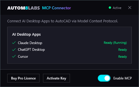
After installation, click the MCP Connector button in the Plug-ins tab to open the connector dialog, then toggle Enable MCP to start the connection. No licence key is needed for the free tools - the key only unlocks the Pro set.
The dialog shows the status of detected AI applications:
- Ready (Running) - The AI application is configured to reach Advance Steel and is currently open
- Ready - Configured, but the application is not running right now
- Detected - The application is installed but not yet configured; toggle Enable MCP to configure it
- Not Detected - The AI application is not installed on this machine
The indicator at the top of the dialog reads Disabled, Waiting, or Active. Toggling Enable MCP off again removes the connector from every detected client's configuration.
Configuration
MCP Connector for Advance Steel includes one-click auto-configuration for supported AI applications. Toggling Enable MCP in the connector dialog writes the configuration for every detected application at once. The installer also registers the server on install, so in most cases there is nothing to do by hand.
Claude Desktop
The config file is located at:
%APPDATA%\Claude\claude_desktop_config.json
The Microsoft Store build never reads %APPDATA%\Claude - Windows redirects that folder into a sandboxed package location. MCP Connector for Advance Steel detects the Store package and writes to both paths, so the Store build is configured automatically. The redirected file lives here:
%LOCALAPPDATA%\Packages\Claude_<hash>\LocalCache\Roaming\Claude\claude_desktop_config.json
If tools still do not appear, fully quit Claude from the system tray (closing the window is not enough) and reopen it.
ChatGPT Desktop
ChatGPT appears in the dialog when it is installed on your machine. The config file is located at:
%USERPROFILE%\.codex\config.toml
This file is shared with the Codex CLI, so configuring ChatGPT Desktop makes the Advance Steel tools available in Codex CLI as well. After configuring, fully quit ChatGPT and reopen it. With Advance Steel open and a drawing loaded, a quick test is to ask ChatGPT to "Check the connection to Advance Steel".
Use a local Work conversation on the computer running Advance Steel. In ChatGPT Desktop, open Settings > MCP servers and check that AUTOM8LABS_AdvanceSteel is enabled, then select Restart. Type /mcp in the conversation to check the connection. ChatGPT in a web browser does not read this local configuration. See the official MCP setup guide.
Cursor
The config file is located at:
%USERPROFILE%\.cursor\mcp.json
GitHub Copilot
GitHub Copilot appears in the dialog when VS Code, Visual Studio, or the Copilot CLI is installed on your machine. The config files are located at:
%APPDATA%\Code\User\mcp.json
%USERPROFILE%\.mcp.json
%USERPROFILE%\.copilot\mcp-config.json
Grok Build
Toggle Enable MCP and the connector writes its entry into xAI's Grok Build CLI configuration automatically. The config file is located at:
%USERPROFILE%\.grok\config.toml
Grok Build also reads Claude Code's and Cursor's MCP config, so if you have already configured either of those the connector shows up in Grok Build with no extra step.
Claude Code & other MCP clients
MCP Connector for Advance Steel exposes a standard MCP stdio server, so it also works with Claude Code, VS Code, and any other MCP-compatible client. The server is a single executable installed with the plug-in bundle:
C:\Program Files\Autodesk\ApplicationPlugins\AUTOM8LABS.MCPConnectorAdvanceSteel.bundle\Contents\Bridge\MCPConnectorAdvanceSteel.Bridge.exe
Register it in Claude Code from a terminal:
claude mcp add AUTOM8LABS_AdvanceSteel -- "C:\Program Files\Autodesk\ApplicationPlugins\AUTOM8LABS.MCPConnectorAdvanceSteel.bundle\Contents\Bridge\MCPConnectorAdvanceSteel.Bridge.exe"
Manual configuration (any MCP client)
Add this to your client's MCP server configuration:
{
  "mcpServers": {
    "AUTOM8LABS_AdvanceSteel": {
      "command": "C:\\Program Files\\Autodesk\\ApplicationPlugins\\AUTOM8LABS.MCPConnectorAdvanceSteel.bundle\\Contents\\Bridge\\MCPConnectorAdvanceSteel.Bridge.exe"
    }
  }
}
VS Code
VS Code uses a slightly different shape. Add the server to your MCP configuration (for example .vscode/mcp.json in a workspace):
{
  "servers": {
    "AUTOM8LABS_AdvanceSteel": {
      "type": "stdio",
      "command": "C:\\Program Files\\Autodesk\\ApplicationPlugins\\AUTOM8LABS.MCPConnectorAdvanceSteel.bundle\\Contents\\Bridge\\MCPConnectorAdvanceSteel.Bridge.exe"
    }
  }
}After changing MCP configuration, restart the AI client completely for the changes to take effect.
Optional: raw command execution
Two tools can drive the host directly: execute_command runs a raw command string as if
typed at the command line, and execute_lisp evaluates an AutoLISP expression. Because they
can drive anything, both are disabled by
default: they are neither listed nor callable until you opt in on that machine by
setting MCP_CONNECTOR_ENABLE_COMMAND_EXEC=1 in the MCP client configuration.
Even when enabled, code-loading and shell verbs (NETLOAD, APPLOAD, SCRIPT, SHELL, AutoLISP
load) are blocked. Both tools are Pro, so a licence is needed as well as the opt-in.
After saving the configuration, fully quit and reopen your AI client - quit it from the system tray rather than just closing the window, or it keeps the old environment and the two tools still will not appear. To turn them off again, remove the setting and restart the client the same way.
{
  "mcpServers": {
    "AUTOM8LABS_AdvanceSteel": {
      "command": "C:\\Program Files\\Autodesk\\ApplicationPlugins\\AUTOM8LABS.MCPConnectorAdvanceSteel.bundle\\Contents\\Bridge\\MCPConnectorAdvanceSteel.Bridge.exe",
      "env": {
        "MCP_CONNECTOR_ENABLE_COMMAND_EXEC": "1"
      }
    }
  }
}
Optional: read-only session
A read-only session withholds every tool that can change a drawing or the steel model. With a Pro licence that leaves 63 tools: the 39 free tools plus the steel queries and exports (objects, assemblies, numbering status, the catalogue, the drawing register, the dimensions and labels on a detail drawing and the material list). A withheld tool is not listed to the AI client at all, and is refused by name if it is called anyway, so the AI cannot reach a write.
It is worth using whenever the drawings belong to a client rather than to you. DWG is usually the format that arrives from someone else. An in-session change can still be undone in Advance Steel, but the folder tools save each drawing as they go, so those edits are on disk already - and an unwanted change does not always announce itself on screen.
Turn it on with the Read-Only Session checkbox in the connection
dialog, or by running MCPCONNECTORADVS_READONLY at the Advance Steel command line.
Either way, reconnect your AI client afterwards so it refreshes its
tool list.
Locking it on for a team. An administrator can enforce read-only across a computer using ForceReadOnly. See Admin Permissions below.
Power BI Dashboard
A separate, free download containing a browser dashboard and Power BI report for tool-use records. The installer includes the audit logger. MCP Connector Pro is required to record audit logs.
Tool Use Audit dashboard
Review AI-assisted work in Advance Steel using a browser dashboard or Power BI.
Requires: MCP Connector for Advance Steel Pro 1.0.0+ and administrator rights to enable logging.
Download: Tool Use Audit v1.0.0 (.zip)
1. Enable logging
Logging is off by default. On each computer, open Registry Editor as administrator. Create this key if needed, then set its values:
HKEY_LOCAL_MACHINE\SOFTWARE\AUTOM8LABS\MCPConnectorAdvanceSteel
| Value name | Type and setting |
|---|---|
AuditLog | DWORD (32-bit): 1 |
AuditLogFolder | String (REG_SZ): your log folder, e.g. C:\AuditLogs |
Create the log folder and give Advance Steel users write access. For multiple computers, use a network share. Restart Advance Steel.
2. Open a dashboard
Extract the ZIP to C:\AuditDashboard or another short path. Keep its files and folders together.
- Open
audit-dashboard.htmlin Chrome or Edge. - Select Open audit folder, choose your
AuditLogFolderand allow read access.
The dashboard reads files locally and refreshes automatically.
- Open
AUTOM8LABS Connector Audit.pbipin Power BI Desktop for Windows (September 2026 or later). - Under Transform data > Edit parameters, set AuditLogFolder to your log folder.
- Select OK > Apply changes > Refresh.
Select Refresh whenever you want the latest records.
3. Check logging works
Ask your AI assistant to run get_drawing_info in your open Advance Steel drawing. Wait around 30 seconds, then check for the call. Select Refresh in Power BI.
Time, user, computer, host and release, drawing, AI app, tool, read/write type and outcome, plus the first 300 characters of its arguments. Chat messages, full tool results and bridge-only connection calls are excluded.
Write means the tool can change a drawing; it does not prove a change occurred. Optional: set AuditReason (DWORD) to 1 in the same registry key, then restart Advance Steel, to request a short explanation from the AI.
CSV files are saved under %LOCALAPPDATA%\AUTOM8LABS\MCPConnectorAdvanceSteel\Audit, then copied into month folders under AuditLogFolder every 30 seconds and when Advance Steel closes. Failed copies retry automatically for files updated within the last seven days.
Local copies are kept for 90 days. Files in your chosen folder are not automatically deleted. Logging is best effort: an unavailable folder or a failed log write does not stop a tool call. See the included README for more detail.
Want your company branding? Contact us.
Claude Desktop Settings
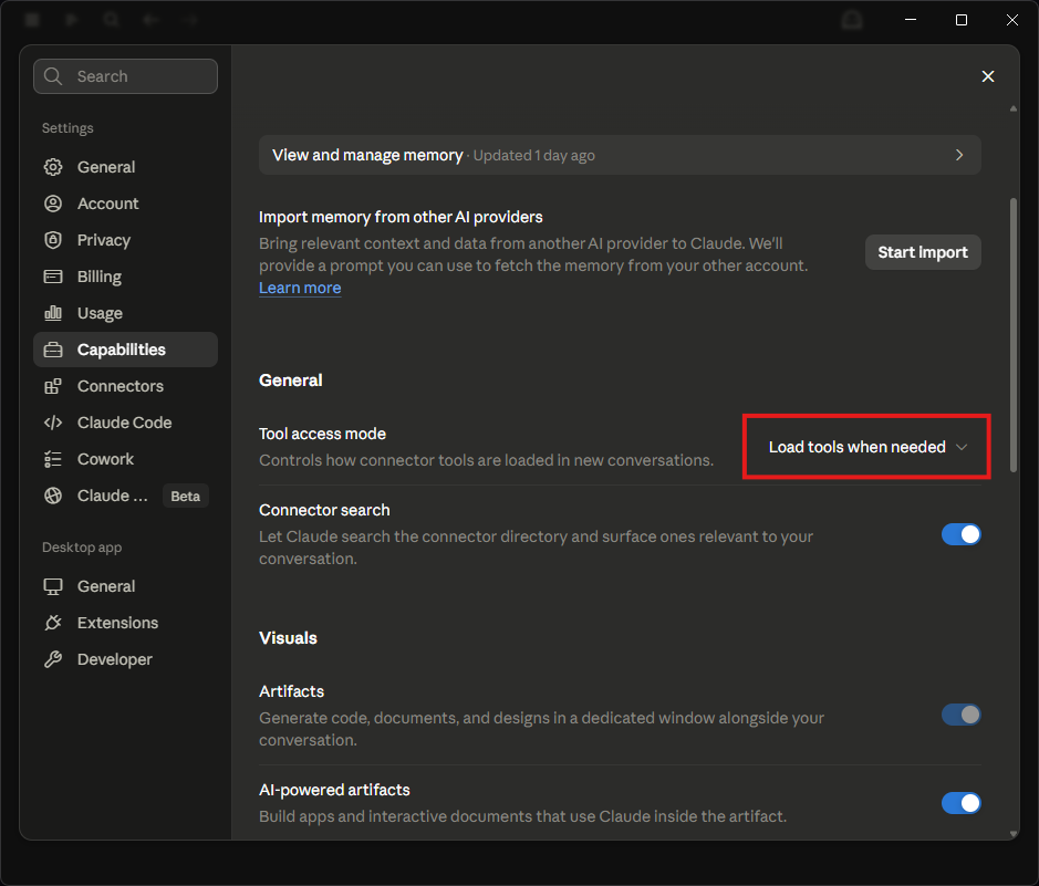
MCP Connector for Advance Steel exposes 224 tools, plus two optional command-execution tools that stay disabled until you opt in. In Claude Desktop, enable Load tools when needed so tools are loaded on demand rather than all at once.
Use Chat, not Cowork
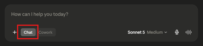
Claude Desktop has a mode selector at the bottom of the message box: Chat and Cowork. MCP connectors run in Chat conversations. In Cowork, your Advance Steel requests will not reach the connector and Claude behaves as if Advance Steel is not connected - even though the connector is configured correctly. Before you start, check the selector is set to Chat.
Note this is the opposite way round to ChatGPT Desktop, where the Advance Steel tools are available in Work rather than regular Chat.
Operator Skill
An operator skill is a plain text playbook Claude reads before touching your drawing. It teaches Claude to use the connector efficiently: read in bulk instead of one entity at a time, verify answers with counts, batch edits in one call, and say so instead of guessing when something cannot be done. The result is fewer calls, fewer dead chats, and far less of your usage allowance burned on a single question.
The free AutoCAD operator skill covers the drawing tools this connector inherits, so it is worth installing. It does not cover the steel tools.
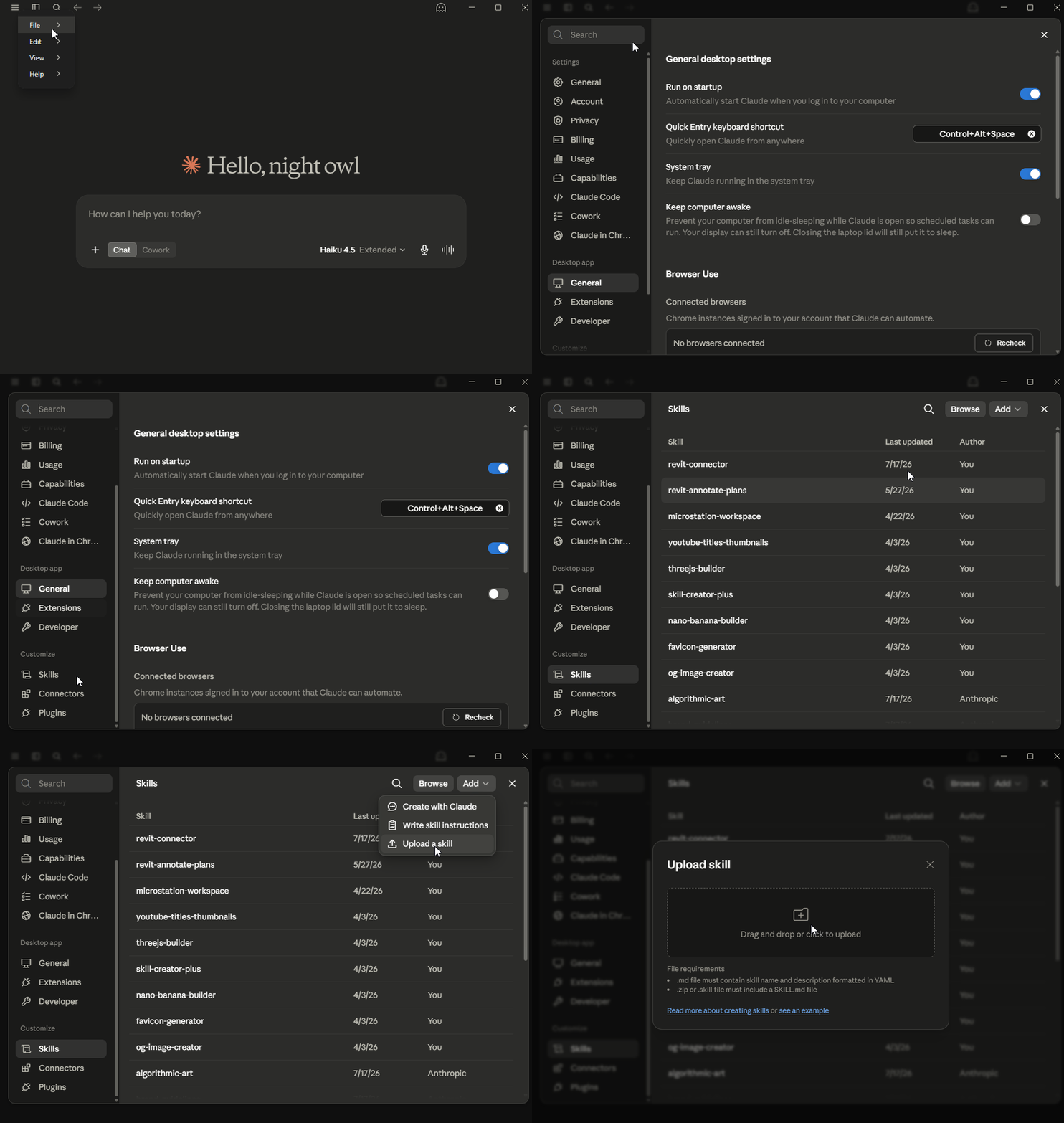
Install in Claude Desktop:
- Download the skill: autocad-connector.zip
- In Claude Desktop, go to Settings > Skills > Add > Upload a skill and select the zip.
- That is it - Claude picks the skill up automatically in new chats. If you ever find it has not, mention it in your prompt, for example "Follow the autocad-connector skill".
Using Claude Code or Cursor instead? Install steps for both are in the mcp-connector-skills repository, which also hosts free skills for the rest of the MCP Connector family.
Quickstart
MCPCONNECTORADVS_STATUS confirms it is running.ping tool. You should get back a confirmation that it is connected.Tool Reference
MCP Connector for Advance Steel serves two sets of tools, grouped by category below. The steel tools come first, then the AutoCAD drawing tools the connector inherits, including a read-only free tier that works without a licence. Every tool name shown is the exact identifier exposed to your AI client. The Edition column shows whether a tool is available in the free edition or needs a Pro licence. A tool marked Opt-in does not register at all until you enable it - see raw command execution. Under each description is an example prompt showing how to ask for it in natural language - click any prompt to copy it, paste it into your AI client, and adjust the names and numbers to suit your drawing.
Steel model and drawings
These tools exist only because the host is Advance Steel. Every one of them needs a Pro
licence. Property changes, section changes, applying an annotation template and deleting
dimensions and labels default to a preview (dry_run: true). Review the proposed
changes before asking the AI to apply them. Numbering, creating drawings, creating beams and
plates, and adding a single dimension or label take effect immediately.
Steel: Model and objects
| Tool | Example prompt | Edition |
|---|---|---|
| Summarise the Advance Steel content of the active drawing | ||
get_steel_document_info | What is in this Advance Steel model? Give me the counts before we start | Pro |
| List the Advance Steel objects in the model as steel objects, not generic entities: beams with section, length and weight; plates with thickness and size; bolt patterns with standard, grade, diameter and count; anchors, welds, shear studs, special parts, grids and connections | ||
list_steel_objects | List every beam with the role Column, with its section, length and assembly mark | Pro |
| Read one Advance Steel object in full by its handle (the steel object's handle or the handle of the entity that draws it): identity, role, material, coating, part mark and assembly mark with their prefixes, quantity in the model, weight, and the geometry that defines it | ||
get_steel_object | Read the full properties of beam 2F3A: section, material, marks and weight | Pro |
| Describe the objects the user has selected in Advance Steel as steel objects: kind, role, section or thickness, material, part mark and assembly mark for each | ||
get_selected_steel_objects | What have I got selected? List each object with its section and marks | Pro |
| Select Advance Steel objects in the drawing by handle so the user can see which ones were meant, replacing the current selection | ||
select_steel_objects | Select the plates you just listed so I can see them in the model | Pro |
| Set properties on one or more Advance Steel objects: material, coating, model role, note, name (denotation), item number, lot or phase, the part mark prefix and assembly mark prefix, layer, and the ten user attributes | ||
set_steel_object_properties | Set the material of every beam with the role Purlin to S355JR, and show me the changes before you apply them | Pro |
| Change the section of one or more existing Advance Steel beams to another size, keeping their position, cuts and connections | ||
change_beam_section | Change the selected rafters to UB457x191x67 and show me the before and after first | Pro |
| Create an Advance Steel straight beam (a beam, column, brace or any straight member) between two points in the model, in millimetres and world coordinates | ||
create_steel_beam | Create a UB254x146x31 beam from 0,0,3000 to 6000,0,3000 with the role Beam | Pro |
| Create an Advance Steel plate in the model, in millimetres and world coordinates | ||
create_steel_plate | Create a 300 by 200 plate, 15 thick, centred at 0,0,0 in S355JR | Pro |
| Read the Advance Steel project data of the model: project name and number, client, building and its location, contractor, order and construction dates, designer, drawn by and the five project user attributes | ||
get_steel_project_data | What project data is set on this model? | Pro |
| Set Advance Steel project data fields on the model | ||
set_steel_project_data | Set the project number to 2417 and the drawn by field to JG | Pro |
Steel: Assemblies and numbering
| Tool | Example prompt | Edition |
|---|---|---|
| List the assemblies in the Advance Steel model, one row per assembly mark: the mark, how many identical assemblies carry it, what the main part is (kind, role, section or thickness, length), how many parts are attached to it in the shop, the total weight of one assembly, and the drawings that already detail it | ||
list_assemblies | List the assemblies whose mark starts with C, with their main part and weight | Pro |
| Read one Advance Steel assembly in full, by its assembly mark or by the handle of any of its parts: the main part, every part attached to it in the shop with its part mark, section or thickness, length, material and weight, the shop bolts and welds that hold it together, the total weight, how many identical assemblies are in the model with the handles of their main parts, and the drawings that detail it | ||
get_assembly | Show me assembly C11 in full: every part, bolt and weld, and the drawings that detail it | Pro |
| Report the numbering state of the Advance Steel model: whether numbering is up to date, how many parts have a part mark and an assembly mark and how many do not, how many distinct part marks and assembly marks exist, the current numbering settings (start numbers, increments and whether single parts and assemblies are numbered), and a sample of the unnumbered parts | ||
get_numbering_status | Is numbering up to date? How many parts have no mark? | Pro |
| Run Advance Steel numbering on the model: identical parts get the same part mark and identical assemblies the same assembly mark, using the prefixes and method configured in Advance Steel. In Advance Steel 2022, run Numbering in Advance Steel itself: the connector reads the marks but cannot start numbering in that release | ||
run_steel_numbering | Run numbering for single parts and assemblies, then tell me how many parts carried marks before and after | Pro |
Steel: Catalogue
| Tool | Example prompt | Edition |
|---|---|---|
| List the section classes in the Advance Steel catalogue installed on this machine (for example UK universal beams, European HEA, square hollow sections), with the shape family of each | ||
list_section_classes | Which section classes are in the catalogue on this machine? | Pro |
| List the section sizes in one Advance Steel section class, with depth, width and weight per metre where the catalogue carries them | ||
list_sections | List the sizes in the universal beams class that start with UB406 | Pro |
| List the materials defined in the Advance Steel catalogue (steel grades and the rest) by the name set_steel_object_properties and the create tools take | ||
list_steel_materials | List the materials that start with S355 | Pro |
| List the model roles defined in the Advance Steel catalogue (Column, Rafter, Purlin, Base plate and so on) by the key set_steel_object_properties and the create tools take, with the description of each | ||
list_steel_roles | Which model roles can I assign? List them with their descriptions | Pro |
Steel: Drawings
| Tool | Example prompt | Edition |
|---|---|---|
| List the documents Advance Steel has generated from this model and registered to it, the contents of the Document Manager: detail drawings, lists and NC files | ||
list_steel_documents | List the detail drawings registered to this model and which assembly each one shows | Pro |
| List the Advance Steel drawing processes installed on this machine | ||
list_drawing_processes | List the drawing processes for selected assemblies and tell me which ones choose their own sheet size | Pro |
| List the Advance Steel drawing styles installed on this machine: the rule sets that decide which views a detail gets and how it is dimensioned and labelled automatically | ||
list_drawing_styles | Which drawing styles are installed for assemblies? | Pro |
| Create Advance Steel detail drawings by running a drawing process, the same as choosing it from the Drawing Processes palette | ||
create_steel_drawings | Create detail drawings for assemblies C10 and C11 using the process I picked | Pro |
| Describe the Advance Steel detail drawing that is open: the model it was generated from, the paper size, each view on the sheet with its position, size and scale and whether it lies on the paper, how many dimensions and labels each view carries, the title texts, and a count of every other Advance Steel detailing object (weld symbols, level symbols, lists, revision table) | ||
get_detail_drawing_info | Describe the detail drawing I have open: sheet size, views and whether any view is off the paper | Pro |
Steel: Dimensions and labels
These tools work on the detail drawing that is open in Advance Steel. Dimensions and labels are created by Advance Steel's own commands, so they are real Advance Steel objects that belong to their view. Linear dimensions and leader labels are read and created. Angular and arc dimensions, level marks, weld symbols and section marks are not. The wording of a new label comes from Advance Steel's label definition for the object it lands on. When a drawing is updated, Advance Steel re-checks manually added dimensions and, with its default settings, can remove them or drop points from them, so add dimensions after the last update or keep them in an annotation template and apply it again afterwards. Labels are not affected.
| Tool | Example prompt | Edition |
|---|---|---|
| List the Advance Steel dimensions on the open detail drawing | ||
list_detail_dimensions | List the dimensions on this drawing, view by view, with the values they show | Pro |
| List the Advance Steel labels on the open detail drawing | ||
list_detail_labels | List the labels on this drawing and what each one says | Pro |
| Read the drawn outline of one view on the open detail drawing as the points a dimension or label can attach to: the end points of its lines (points) and the centres of its holes (holes), in sheet millimetres | ||
get_detail_view_geometry | Give me the points and hole centres of view 2 so we can dimension it | Pro |
| Add an Advance Steel dimension to a view on the open detail drawing, the same object the Labels & Dimensions commands create, so it belongs to the view | ||
add_detail_dimension | Add a chain dimension along the bottom of view 1 through every hole centre | Pro |
| Add an Advance Steel label to an object in a view on the open detail drawing, the same object the Insert Label command creates | ||
add_detail_label | Label the end plate in view 3 and put the text to the right of it | Pro |
| The outcome of the most recent add_detail_dimension, add_detail_label or apply_annotation_template in this Advance Steel session | ||
get_detail_annotation_report | Did those dimensions and labels get created? Show me the outcome of each one | Pro |
| Delete Advance Steel dimensions and labels from the open detail drawing by handle (from list_detail_dimensions and list_detail_labels) | ||
delete_detail_annotations | Delete the two vertical dimensions on view 1, and show me what would go first | Pro |
Steel: Annotation templates
A template holds the dimensions and labels of one finished drawing, each stored relative to its view. Applying it to the drawing of a similar assembly moves each point onto the nearest real point of the same sort and reports anything that has no match. It is a matching rule for similar assemblies, not a guarantee: check the result. Applying a template again adds only what is missing.
| Tool | Example prompt | Edition |
|---|---|---|
| Save the dimensions and labels of the open Advance Steel detail drawing as a named annotation template, so the same dimensioning and labelling can be applied to drawings of similar assemblies with apply_annotation_template | ||
save_annotation_template | Save the dimensions and labels of this drawing as a template called column-base | Pro |
| List the annotation templates saved on this machine with save_annotation_template: name, the drawing each was saved from, when, and how many views, dimensions and labels it holds | ||
list_annotation_templates | Which annotation templates are saved on this machine? | Pro |
| Put the dimensions and labels of a saved annotation template onto the open Advance Steel detail drawing, re-creating each with Advance Steel's own dimension and label commands at the matching place in this drawing's views | ||
apply_annotation_template | Preview the column-base template on this drawing and tell me what has no match | Pro |
Steel: Export
| Tool | Example prompt | Edition |
|---|---|---|
| Build a material list of the Advance Steel model grouped by part mark: mark, quantity, kind, section or plate thickness, length, width, material, coating, weight each and total weight, and the assembly marks the part appears in | ||
export_steel_material_list | Build a material list grouped by part mark and save it as a spreadsheet in the job folder | Pro |
Connectivity
| Tool | Example prompt | Edition |
|---|---|---|
| Check that the AI client can reach a running Advance Steel session | ||
ping | Ping Advance Steel and tell me if you are connected | Free |
Drawing and Document
| Tool | Example prompt | Edition |
|---|---|---|
| Audit the drawing database and optionally fix errors | ||
audit_drawing | Audit this drawing and fix any database errors you find | Pro |
| Copy entities and paste them at their original coordinates, within or between drawings | ||
copy_to_original_coordinates | Copy the selected setting-out lines into Site-Plan.dwg at their original coordinates | Pro |
| Mark a point to roll back to, optionally saving a copy of the drawing first | ||
create_checkpoint | Set a checkpoint and save a backup copy before you start the layer clean-up | Pro |
| Detect likely drawing units by inspecting extents, entity sizes, and system variables | ||
detect_units | This survey DWG has no units set - work out what the units really are from the extents and entity sizes | Free |
| Read drawing information: file path, units, extents, layer and entity counts | ||
get_drawing_info | What are the units, extents, and layer and entity counts for this drawing? | Free |
| Read the value of a system variable | ||
get_system_variable | What is DIMSCALE set to in this drawing? | Free |
| Create a new blank drawing, optionally from a template | ||
new_drawing | Start a new drawing from our A1 template at C:\Standards\A1-Sheet.dwt | Pro |
| Open a DWG, DXF or DWT file, or switch to it if already open | ||
open_drawing | Open C:\Project\DWG\Site-Plan.dwg | Pro |
| Purge unused named objects to reduce file size | ||
purge_drawing | Purge every unused block, layer, and style from this drawing | Pro |
| Redo is unavailable in this Advance Steel connector. Save a separate DWG copy before undo if you may need the current state again. | ||
redo | Explain why redo is unavailable in Advance Steel | Pro |
| Revert changes since the last checkpoint. This rollback cannot be redone; save a separate copy first if needed. | ||
rollback_checkpoint | That has gone wrong, roll everything back to the checkpoint | Pro |
| Save the drawing, optionally to a new DWG or DXF path | ||
save_drawing | Save this drawing as a 2018 format DWG to C:\Project\Issue\Plan-A.dwg | Pro |
| Set a system variable to a new value | ||
set_system_variable | Set LTSCALE to 0.5 and turn FILEDIA back on | Pro |
| Set linear and angular units, insertion scale, and display precision | ||
set_units | Set this drawing to millimetres with 2 decimal places and degrees for angles | Pro |
| Undo the last changes, one tool call per step. Redo is unavailable; save a separate copy first if needed. | ||
undo | Undo the last three things you did | Pro |
Entities and Selection
| Tool | Example prompt | Edition |
|---|---|---|
| Delete a named selection set; the entities themselves are untouched | ||
delete_selection_set | Delete the saved selection set called Fire strategy | Pro |
| List entities, filtered by type, layer, or bounding box, with pagination | ||
get_entities | List every polyline on the layer A-WALL with its layer and geometry | Free |
| Read full details of a specific entity by its handle | ||
get_entity_by_handle | Give me the full details of entity 2A7F | Free |
| Count entities, optionally broken down by type or layer | ||
get_entity_count | How many entities are in this drawing, broken down by layer? | Free |
| Read the full property set of one or more entities | ||
get_entity_properties | Read the full properties of the selected entities including linetype and lineweight | Free |
| Read the entities currently selected in Advance Steel | ||
get_selected_entities | What have I got selected right now? | Free |
| Extract portable geometry data (lines, polylines, arcs, circles, ellipses, splines) from the current selection | ||
get_selected_geometry | Extract the geometry of my selection as coordinates so we can work with it | Pro |
| Count the entities in the current selection | ||
get_selection_count | How many entities are in my current selection? | Free |
| List the named selection sets saved in the drawing, with how many of their entities still exist | ||
list_selection_sets | What selection sets are saved in this drawing? | Free |
| Select the entities of a named selection set so the next tool acts on them | ||
recall_selection_set | Select everything in the saved set called Fire strategy | Pro |
| Save the current selection, or a list of handles, as a named set stored in the drawing | ||
save_selection_set | Save what I have selected as a set called Fire strategy | Pro |
Geometry Creation
| Tool | Example prompt | Edition |
|---|---|---|
| Create an arc from centre, radius and angles, or from three points | ||
create_arc | Draw an arc through the points 0,0 then 1000,500 then 2000,0 | Pro |
| Trace the closed boundary around a point, with islands, and keep it as a polyline | ||
create_boundary | Trace the outline of the room I am pointing at, at 4200,3100, and keep the boundary | Pro |
| Create a circle from centre point and radius | ||
create_circle | Draw a 450 radius circle at 2500,3000 on layer S-COLS | Pro |
| Create an ellipse from centre, major axis endpoint, and axis ratio | ||
create_ellipse | Draw an ellipse at 5000,5000 with a 2000 major axis and a 0.5 axis ratio | Pro |
| Create a hatch fill inside a closed boundary, including solid and gradient fills | ||
create_hatch | Hatch inside the selected boundary with ANSI31 at scale 25 | Pro |
| List the hatch pattern names create_hatch can use: patterns already carried by hatches in the drawing, plus the predefined names from the pattern file in force | ||
list_hatch_patterns | Which hatch patterns can I use in this drawing? | Free |
| Create a line between two points | ||
create_line | Draw a line from 0,0 to 5000,0 on the layer A-GRID | Pro |
| Create multiline text with formatting, width wrapping, and text styles | ||
create_mtext | Add a note at 1000,500 reading All dimensions to be checked on site, wrapped to 3000 wide | Pro |
| Create a NURBS spline from full B-spline data (degree, control points, knots, weights) | ||
create_nurbs_curve | Create a degree 3 NURBS curve from these control points and knots | Pro |
| Create a 2D or 3D polyline, with arc segments, widths, and closure | ||
create_polyline | Draw a closed polyline through 0,0 then 6000,0 then 6000,4000 then 0,4000 on layer A-WALL | Pro |
| Create a rectangle as a closed polyline from two opposite corners | ||
create_rectangle | Draw a rectangle from 0,0 to 10000,6000 on layer A-ROOM | Pro |
| Create a spline through fit points or from control points | ||
create_spline | Draw a spline through 0,0 then 1000,800 then 2500,400 then 4000,1200 | Pro |
| Create single-line text | ||
create_text | Put the text GA PLAN at 500,200 at 350 high | Pro |
3D Solids
| Tool | Example prompt | Edition |
|---|---|---|
| Keep the common volume of two solids | ||
boolean_intersect | Keep only the volume where those two solids overlap | Pro |
| Subtract one solid from another | ||
boolean_subtract | Subtract the door opening solid from the wall solid | Pro |
| Unite two 3D solids into one | ||
boolean_union | Union the two selected solids into one | Pro |
| Create a solid box from a corner point and dimensions | ||
create_3d_box | Create a solid box at 0,0,0 measuring 6000 by 4000 by 3000 | Pro |
| Create a solid cone from base centre, base radius, and height | ||
create_3d_cone | Create a cone at 0,0 with a 750 base radius and 2000 height | Pro |
| Create a solid cylinder from centre point, radius, and height | ||
create_3d_cylinder | Create a 300 radius column 3600 tall at 2000,2000 | Pro |
| Create a solid sphere from centre point and radius | ||
create_3d_sphere | Create a 500 radius sphere at 1000,1000,2000 | Pro |
| Create a solid torus from centre, major radius, and minor radius | ||
create_3d_torus | Create a torus at 0,0,1000 with a 1500 major radius and a 100 tube radius | Pro |
| Create a solid wedge from a corner point and dimensions | ||
create_3d_wedge | Create a wedge at 0,0,0 measuring 2000 by 1000 by 800 | Pro |
| Extrude a closed 2D profile into a solid along a direction or path | ||
create_extrusion | Extrude the selected closed polyline up 3000 to make a wall solid | Pro |
| Create a cross-section region where a plane intersects a solid | ||
section_solid | Cut a horizontal section region through the solid at 1200 above its base | Pro |
| Slice a solid with a plane, optionally keeping both halves | ||
slice_solid | Slice the solid vertically at X=3000 and keep both halves | Pro |
Modification
| Tool | Example prompt | Edition |
|---|---|---|
| Align entities by mapping source points to destination points | ||
align_entities | Align the selected detail so its two corner points land on the two points I have picked | Pro |
| Create a circular array around a centre point | ||
array_polar | Array the selected bolt 8 times around 0,0 | Pro |
| Create a rectangular array with rows, columns, and spacing | ||
array_rectangular | Array the selected column 5 columns by 3 rows at 6000 spacing both ways | Pro |
| Break an entity at one point or between two points | ||
break_entity | Break the selected line between 2000,0 and 3000,0 | Pro |
| Create an angled corner between two entities with distances | ||
chamfer_entities | Chamfer the corner between those two lines at 25 by 25 | Pro |
| Change common entity properties: layer, colour, linetype, lineweight, transparency | ||
change_entity_properties | Move the selection onto layer A-ANNO and set its colour back to ByLayer | Pro |
| Convert lines, arcs, or splines into a single polyline | ||
convert_to_polyline | Convert the selected lines and arcs into a single polyline | Pro |
| Copy entities by a displacement vector | ||
copy_entities | Copy the selected block 1200 along X, four times | Pro |
| Create a region from closed coplanar curves | ||
create_region | Make a region from the selected closed boundary | Pro |
| Edit a polyline in place: vertices, bulge, global width, direction, or fillet every corner | ||
edit_polyline | Set the red line boundary to 0.7 wide and round all its corners at 500 radius | Pro |
| Delete entities from the drawing permanently | ||
erase_entities | Delete the selected entities | Pro |
| Explode a compound entity (block reference, polyline, dimension, hatch) into its parts | ||
explode_entity | Explode the selected block into its parts | Pro |
| Extend an entity to meet a boundary edge | ||
extend_entity | Extend that line so it meets the wall line | Pro |
| Create a rounded corner between two entities with a radius | ||
fillet_entities | Fillet those two lines with a 50 radius | Pro |
| Join contiguous lines, arcs, or polylines into a single polyline | ||
join_entities | Join the selected lines and arcs into one polyline | Pro |
| Lengthen or shorten a curve by a delta distance | ||
lengthen_entity | Lengthen the selected line by another 500 | Pro |
| Copy properties from one entity onto others, with per-property control | ||
match_properties | Make the new dimensions match the formatting of the one on grid A | Pro |
| Mirror entities across a line defined by two points | ||
mirror_entities | Mirror the selected entities about a vertical line at X=5000 and keep the originals | Pro |
| Move entities by a displacement vector | ||
move_entities | Move the selected entities 2500 in X and nothing in Y | Pro |
| Create an offset copy of a curve at a specified distance | ||
offset_entity | Offset the selected polyline 100 towards the inside | Pro |
| Rotate entities around a base point by an angle | ||
rotate_entities | Rotate the selection 90 degrees around 0,0 | Pro |
| Scale entities relative to a base point by a uniform factor | ||
scale_entities | Scale the selection up by 1.5 about the point 0,0 | Pro |
| Bring entities to front or send them to back, or place them above or below another entity | ||
set_draw_order | Send that hatch behind the walls so the linework reads again | Pro |
| Stretch what a crossing window touches, moving only the vertices inside it | ||
stretch_entities | Widen the kitchen opening by 300 by stretching everything in that window | Pro |
| Trim an entity at boundary edges defined by other entities | ||
trim_entity | Trim that line back to the two boundary lines I have selected | Pro |
Layers
| Tool | Example prompt | Edition |
|---|---|---|
| Create a new layer with specified properties | ||
create_layer | Create a layer called A-GLAZ in colour 4 with the DASHED linetype | Pro |
| Delete a saved layer state | ||
delete_layer_state | Delete the old DEMOLITION layer state | Pro |
| Freeze one or more layers | ||
freeze_layer | Freeze the layers XREF-SITE and XREF-SERV | Pro |
| List saved layer states with their descriptions and layers | ||
list_layer_states | What layer states are saved in this drawing? | Free |
| List all layers with colour, linetype, lineweight, state, and description | ||
list_layers | List every layer with its colour, linetype, and whether it is frozen or locked | Free |
| Lock one or more layers against editing | ||
lock_layer | Lock the survey layers so nobody edits them by accident | Pro |
| Restore a saved layer state, globally or into one viewport | ||
restore_layer_state | Apply the PROPOSED layer state to the viewport on sheet 03 | Pro |
| Save the current layer settings as a named layer state | ||
save_layer_state | Save these layer settings as EXISTING | Pro |
| Set the current layer for new entities | ||
set_current_layer | Make A-WALL the current layer | Pro |
| Modify or rename an existing layer, including on or off, frozen and locked (a viewport on an off layer keeps its view and loses its frame) | ||
set_layer_properties | Change layer A-ANNO to colour 7 and turn its plot flag off | Pro |
| Thaw one or more layers | ||
thaw_layer | Thaw all the frozen layers | Pro |
| Unlock one or more layers | ||
unlock_layer | Unlock layer S-GRID | Pro |
Blocks
| Tool | Example prompt | Edition |
|---|---|---|
| Count insertions of a block, optionally grouped by layer | ||
count_block_references | How many door blocks are in this drawing, grouped by layer? | Free |
| Create a new block definition from existing entities | ||
create_block_definition | Turn the selected entities into a block called DETAIL-01 with its base point at 0,0 | Pro |
| Read attribute definitions and values from a block reference | ||
get_block_attributes | Read the attributes off the selected title block | Free |
| Read a dynamic block's visibility states, flips, lookups and sizes, with the values each allows | ||
get_dynamic_block_properties | What sizes and swing options does that door block offer? | Free |
| Import block definitions from another DWG, with the unit scale handled, and place them in the same call | ||
import_blocks | Bring the door and window blocks in from the office library DWG and place a 900 door at 4500,2000 | Pro |
| Insert a block reference with scale, rotation, and attribute values | ||
insert_block | Insert the DOOR-900 block at 4500,2000 rotated 90 degrees | Pro |
| List block definitions with entity counts, attributes, and xref status | ||
list_blocks | List every block in this drawing with how many entities it has and whether it carries attributes | Free |
| Rename a block definition, with every reference following it | ||
rename_block | Rename the block DOOR-01 to DOOR-EXTERNAL | Pro |
| Swap block references from one definition to another, keeping position, rotation and attributes | ||
replace_block | Replace every WINDOW-OLD block with WINDOW-2G and keep the attributes | Pro |
| Set an attribute value on a block reference by tag name | ||
set_block_attribute | Set the DRAWN_BY attribute on the selected title block to JG | Pro |
| Set a dynamic block's visibility state, size, flip or lookup value | ||
set_dynamic_block_properties | Change that door to 900 wide with the swing flipped | Pro |
Annotation
| Tool | Example prompt | Edition |
|---|---|---|
| Create an aligned dimension measuring true distance at any angle | ||
create_dimension_aligned | Add an aligned dimension along the sloping wall between those two ends | Pro |
| Create an angular dimension between two lines or from three points | ||
create_dimension_angular | Dimension the angle between the two selected lines | Pro |
| Create a horizontal or vertical dimension between two points, or a whole chain along a wall with the overall in one call | ||
create_dimension_linear | Dimension horizontally between 0,0 and 6000,0 with the dimension line at 0,-800 | Pro |
| Create a radius or diameter dimension on a circle or arc | ||
create_dimension_radius | Add a radius dimension to the selected arc | Pro |
| Create a multileader with an arrow and text annotation | ||
create_leader | Add a leader pointing at 3200,1800 with the text 150mm blockwork | Pro |
| Draw a revision cloud around a rectangle, a polygon, or an existing closed entity | ||
create_revcloud | Cloud the area around the revised bathroom layout | Pro |
| Create a table in a table style with rows, columns and cell data, per-table text heights and margins, and a read-back of the laid-out format | ||
create_table | Create a 6 row by 4 column door schedule at 12000,0 with the headers Mark, Width, Height, Type | Pro |
| Create a wipeout mask so annotation stays legible over hatching | ||
create_wipeout | Put a wipeout behind that note so it reads over the hatch | Pro |
| List the annotation scales defined in the drawing and which one is current | ||
list_annotation_scales | What annotation scales does this drawing have? | Free |
| Make text, dimensions and multileaders annotative and give them the scale representations they appear at | ||
set_annotative | Make the room notes annotative at 1:50 and 1:100 | Pro |
Views and Navigation
| Tool | Example prompt | Edition |
|---|---|---|
| Capture the current viewport to an image file | ||
capture_screenshot | Capture the current view to C:\Temp\check.png and tell me what you can see | Pro |
| Delete a named view | ||
delete_view | Delete the saved view called OLD-SITE | Pro |
| List named views with direction, target, and visual style | ||
list_views | List the named views saved in this drawing | Free |
| Restore a named view | ||
restore_view | Go back to the SITE-ENTRANCE view | Pro |
| Save the current view under a name so it can be restored later | ||
save_view | Save this view as SITE-ENTRANCE | Pro |
| Set the visual style of the current viewport | ||
set_visual_style | Switch the viewport to a shaded visual style | Pro |
| Zoom the viewport to show everything in the drawing | ||
zoom_extents | Zoom out so I can see the whole drawing | Free |
| Zoom to specific entities with optional padding | ||
zoom_object | Zoom to the selected entities with a bit of padding around them | Free |
| Zoom to a rectangular window defined by two corners | ||
zoom_window | Zoom into the area between 0,0 and 10000,8000 | Free |
Layouts and Plotting
| Tool | Example prompt | Edition |
|---|---|---|
| Create several sheets from a template layout with viewport scales, view centres, layer states and title texts set, validated first, one undo step | ||
create_sheets_from_layout | Make sheets 01 to 04 from the A3 template, each viewport at 1:100 on its own block, with the titles filled in | Pro |
| Create a viewport in the current paper space layout | ||
create_viewport | Add a viewport on this layout at 150,100 measuring 250 by 180 at 1:100 | Pro |
| Delete a paper space layout and everything on it | ||
delete_layout | Delete the spare sheet called Layout2 | Pro |
| Copy a layout including its title block, viewports and page setup | ||
duplicate_layout | Copy the A3 template sheet four times for drawings 01 to 04 | Pro |
| Read a layout's plot device, paper size, scale, rotation and plot style table, and where the sheet edge and printable area sit in paper coordinates | ||
get_page_setup | What paper size and plot style is sheet 02 set up for? | Free |
| List layouts with page setup, paper size, and viewport count | ||
list_layouts | List the layouts in this drawing with their paper sizes and viewport counts | Free |
| ISO, JIS, ANSI and ARCH sheet sizes with the plotter's media names, and the metric and imperial scale tables | ||
list_paper_sizes | Which media name is ARCH D landscape on this plotter, and what is 1/4 inch to the foot as a ratio? | Free |
| List the viewports on a layout with scale, position, lock state and frozen layers | ||
list_viewports | List the viewports on sheet 03 with their scales | Free |
| Plot a layout to a PDF file | ||
plot_to_pdf | Plot the A101 layout to C:\Project\Issue\A101.pdf | Pro |
| Rename a paper space layout tab | ||
rename_layout | Rename Layout1 to 01 - SITE LOCATION PLAN | Pro |
| Switch to a layout tab or back to model space | ||
set_current_layout | Switch to the layout called A101 | Pro |
| Set a layout's plot device, paper size and orientation, plot style table with its display and plot flags, scale, rotation and centring; reads back where the paper sits | ||
set_page_setup | Set every sheet to DWG To PDF at A3 with monochrome.ctb | Pro |
| Set a viewport's scale, the model point it shows, its size on the sheet, twist and lock | ||
set_viewport | Set that viewport to 1:100 centred on the barn, then lock it | Pro |
| Freeze or thaw layers in one viewport only, leaving other sheets untouched | ||
set_viewport_layers | Freeze the DEMOLITION layer in the proposed sheet viewport only | Pro |
Styles
| Tool | Example prompt | Edition |
|---|---|---|
| Create a new dimension style, refusing a name that already exists | ||
create_dimension_style | Create a dimension style called A3-1-50 with 2.5 mm text, 2 mm arrows and annotative scaling | Pro |
| Create a new table style: text height, text style and alignment per row type, cell margins and flow direction | ||
create_table_style | Create a compact schedule style with 2 mm text and 0.5 mm margins | Pro |
| Create a new text style, refusing a name that already exists | ||
create_text_style | Create an annotative text style called Notes using Arial | Pro |
| List dimension styles with their key settings | ||
list_dimension_styles | List the dimension styles with their text heights and arrow sizes | Free |
| List loaded linetypes with descriptions and scale factors | ||
list_linetypes | What linetypes are loaded in this drawing? | Free |
| List table styles with their title, header and data row formatting and margins | ||
list_table_styles | What table styles are in this drawing and what text heights do they use? | Free |
| List text styles with font, height, and width factor | ||
list_text_styles | List the text styles with their fonts and heights | Free |
| Load a linetype from a .lin file into the drawing | ||
load_linetype | Load the CENTER and DASHDOT linetypes from acadiso.lin | Pro |
| Create or modify a dimension style: text height, arrows, decimals, overall scale and more | ||
set_dimension_style | Create a dimension style for 1:100 with 250 text and no decimals | Pro |
| Change an existing table style; tables using it follow | ||
set_table_style | Make the data rows in the Schedule style 1.8 mm text | Pro |
| Create or modify a text style: font, height, width factor, oblique angle, bold and italic | ||
set_text_style | Create a text style called NOTES using Arial at 250 high | Pro |
External References
| Tool | Example prompt | Edition |
|---|---|---|
| Attach a raster image such as an OS extract, aerial or scanned survey, sized in drawing units | ||
attach_image | Attach the OS extract at 0,0 and scale it so the site frontage measures 42 m | Pro |
| Attach a page of a PDF as an underlay to trace or check against | ||
attach_pdf_underlay | Bring in page 2 of the topo survey PDF as an underlay | Pro |
| Attach an external DWG as a reference (attach or overlay) | ||
attach_xref | Attach C:\Project\DWG\Site.dwg as an overlay at 0,0 | Pro |
| Scale an attached image, and any traced linework, so two picked points are a known distance apart | ||
calibrate_image | Scale the scanned plan so the grid bay I picked measures 6000 | Pro |
| Clip an xref, image or PDF underlay to a rectangle or polygon | ||
clip_underlay | Clip the aerial photo to just the red line boundary | Pro |
| Detach an external reference completely | ||
detach_xref | Detach the SERVICES xref completely | Pro |
| Read the clip boundary of an xref, image or PDF underlay in drawing coordinates | ||
get_clip_boundary | Is the aerial photo clipped, and where does its boundary run? | Free |
| List external references with paths, status, type, and insertion details | ||
list_xrefs | List the xrefs in this drawing and flag any that are not found | Free |
| Reload external references to pick up source file changes | ||
reload_xref | Reload all the xrefs so I pick up the latest changes | Pro |
| Adjust fade, contrast, brightness, monochrome and visibility of an image or underlay | ||
set_image_display | Fade the survey underlay to 50 percent so my linework reads over it | Pro |
| Trace an attached scan, sketch or photograph into polylines, arcs or splines placed over the image | ||
trace_image | Trace the scanned ground floor plan into linework, then trace the facade in the site photo for context | Pro |
UCS
| Tool | Example prompt | Edition |
|---|---|---|
| Read the current UCS origin and axis vectors | ||
get_ucs | What is the current UCS origin and orientation? | Free |
| List all named UCS entries in the drawing | ||
list_ucs | List the named UCS entries in this drawing | Free |
| Set the UCS from an origin and optional axis directions | ||
set_ucs | Set the UCS origin to 5000,3000 and rotate it 30 degrees | Pro |
Search and Text
| Tool | Example prompt | Edition |
|---|---|---|
| Count occurrences of one or more text patterns | ||
count_text_patterns | Count how many times FFL and SSL appear in this drawing | Pro |
| Search text and attribute values across the drawing | ||
find_text | Find every occurrence of PROVISIONAL in the drawing text and block attributes | Pro |
| Temporarily highlight entities by colour, with restore | ||
highlight_entities | Highlight those entities in red so I can see where they are | Pro |
| Isolate entities by turning off all other layers | ||
isolate_entities | Isolate the selected entities so everything else is hidden | Pro |
| Find and replace text in MText, single-line text, and attributes | ||
replace_text | Replace Rev A with Rev B everywhere in this drawing | Pro |
| Select entities matching property filters | ||
select_by_filter | Select every red polyline on the layer A-WALL | Pro |
| Restore layer states after an isolate operation | ||
unisolate_layers | Put the layers back how they were before I isolated | Pro |
Utility and Measurement
| Tool | Example prompt | Edition |
|---|---|---|
| Run a raw command string as if typed at the command line (does not register until you opt in). Code-loading and shell verbs are blocked. | ||
execute_command | Run the REGENALL command | ProOpt-in |
| Evaluate an AutoLISP expression and return the result (disabled by default; see opt-in). Code-loading and shell forms are blocked. | ||
execute_lisp | Evaluate the AutoLISP expression (getvar "DWGNAME") and tell me the result | ProOpt-in |
| Read the axis-aligned bounding box of one or more entities | ||
get_bounding_box | What is the overall bounding box of the selected entities? | Free |
| Measure areas and place a label at each one, kept clear of door swings and fittings, with an optional schedule table and total | ||
label_areas | Label each room with its floor area in square metres and add a schedule with the total | Pro |
| Measure area and perimeter of a closed entity or point polygon | ||
measure_area | What is the area and perimeter of the selected closed polyline? | Free |
| Measure several closed areas at once, by handle or by a point inside each, converted to square metres or square feet | ||
measure_areas | Give me the floor area of each of these three units in square metres, and the total | Free |
| Measure the distance and angle between two points | ||
measure_distance | What is the distance and angle between 0,0 and 4500,3200? | Free |
| Run a list of tool calls in one round trip as one undo step, each result returned in order | ||
run_batch | Draw all twelve wall segments and hatch them in one go | Pro |
Management Pack
Folder-batch tools for whole-project maintenance. Each one runs over every drawing in a folder using a side database, so your open drawing is never disturbed. Write operations are safe by default: a dry-run mode previews what would change without modifying any file.
| Tool | Example prompt | Edition |
|---|---|---|
| Write a revision letter, date and description into title blocks across chosen layouts or a whole folder | ||
add_revision_to_layouts | Stamp revision P02 dated 28.08.26 "Planning issue" on every sheet in C:\Project\DWG - dry run first | Pro |
| Run a maintenance operation (purge, audit, downsave and more) over every drawing in a folder | ||
batch_process_folder | Purge and audit every drawing in C:\Project\DWG - dry run first | Pro |
| Bind external references into every drawing, saving bound copies to an output folder | ||
bind_xrefs | Bind the xrefs in every drawing in C:\Project\DWG and save the bound copies to C:\Project\Issue - dry run first | Pro |
| Extract block attribute values across a folder to Excel or CSV for schedules and bills of materials | ||
block_attribute_extract | Extract every door block attribute across C:\Project\DWG to C:\Project\door-schedule.xlsx, grouped and counted | Pro |
| Write a per-drawing health report (size, version, counts, broken references) to Excel or CSV | ||
drawing_health_report | Write a health report for every drawing in C:\Project\DWG to C:\Project\health.xlsx | Pro |
| Plot every layout of every drawing in a folder to PDF | ||
dwg_folder_to_pdf | Plot every layout in C:\Project\DWG to PDF, one file per drawing, into C:\Project\Issue - dry run first | Pro |
| Build a drawing register from title-block attributes, one row per drawing and layout, to Excel or CSV | ||
export_drawing_register | Build a drawing register from C:\Project\DWG to C:\Project\register.xlsx | Pro |
| Report proxy objects by class and application across a folder | ||
find_proxy_objects | Report any proxy objects across C:\Project\DWG and write it to C:\Project\proxies.xlsx | Pro |
| Write a layer inventory across a folder to Excel or CSV for standards auditing | ||
layer_report_to_excel | Write a layer inventory for every drawing in C:\Project\DWG to C:\Project\layer-audit.xlsx | Pro |
| Merge source layers into a target layer across a folder, then erase the emptied layers | ||
merge_layers | Merge the layers OLD-WALL and WALL-2 into A-WALL across C:\Project\DWG - dry run first | Pro |
| Erase zero-length and degenerate entities across a folder, with per-file counts | ||
purge_zero_length | Erase the zero length lines and whitespace-only text across C:\Project\DWG - dry run first | Pro |
| Attach a standard set of external references to every drawing in a folder | ||
reattach_xref_set | Attach the project grid and site base xrefs to every drawing in C:\Project\DWG at 0,0 on layer X-REF - dry run first | Pro |
| Apply an old-to-new layer mapping from Excel or CSV to every drawing in a folder | ||
remap_layers_from_excel | Apply the layer mapping in C:\Standards\layer-map.xlsx to every drawing in C:\Project\DWG - dry run first | Pro |
| Fix external reference paths across a folder after a project move | ||
repath_xrefs | The project moved from P:\Old to P:\New - repath the xrefs across C:\Project\DWG by replacing the root, dry run first | Pro |
| Remove excess annotation scales from every drawing in a folder | ||
scale_list_cleanup | Strip every annotation scale except 1:50 and 1:100 from the drawings in C:\Project\DWG - dry run first | Pro |
| Update title block attribute values across a folder, from an inline map or an Excel/CSV sheet | ||
title_block_update | Update the title block attributes across C:\Project\DWG from the sheet at C:\Project\Register.xlsx - dry run first | Pro |
| Update an existing drawing register in place, keeping its formatting, adding an issue column for the revision | ||
update_drawing_register | Add a 28.08.26 issue column to C:\Project\register.xlsx from the drawings in C:\Project\DWG - dry run first | Pro |
| Audit broken, unloaded, nested, and circular external references project-wide | ||
xref_report | Audit the xrefs across C:\Project\DWG and tell me what is broken, unloaded, or circular | Pro |
FAQ
MCPCONNECTORADVS_LICENCE command, then restart your AI client.
Changelog
First public release
- New drawings. Drawing-register queries handle native initialisation without saving changes or clearing existing edits
- Safer updates. Silent setup checks for a running CAD host or locked bridge before removing installed files
- Administration. Pro audit logging, HTML and Power BI reports, registry allow/block lists and enforced read-only sessions
- Steel model. Read beams, plates, bolts, anchors and welds as steel objects with their sections, materials, roles, marks and weights, and read an assembly with every part attached to it in the shop
- Numbering and drawings. Report the numbering state, run numbering, create detail drawings with a drawing process and list the documents registered to the model
- Dimensions and labels. Read the dimensions and labels on a detail drawing and add real Advance Steel dimensions and labels to its views
- Annotation templates. Save the dimensions and labels of a finished drawing and apply them to the drawings of similar assemblies
- Editing. Set material, coating, role and other properties, change beam sections, and create beams and plates
- Material list grouped by part mark, with the bolts on a second sheet, exported to a spreadsheet
- The AutoCAD drawing tools are included, so inside Advance Steel this is the only connector you need
- Bulk edits preview before they write and report what they would change
- Advance Steel 2022 to 2027